Eng-Tips is the largest engineering community on the Internet

Intelligent Work Forums for Engineering Professionals

Modeling effect of Ring Type Joint Rings on RTJ Grooves

Status
Not open for further replies.

bryansonnier

Mechanical
Dec 20, 2011
80
0
0
US
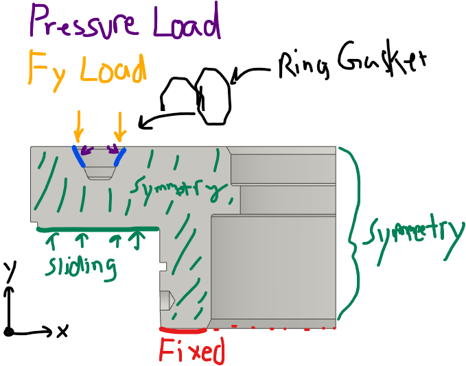
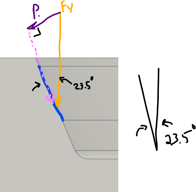
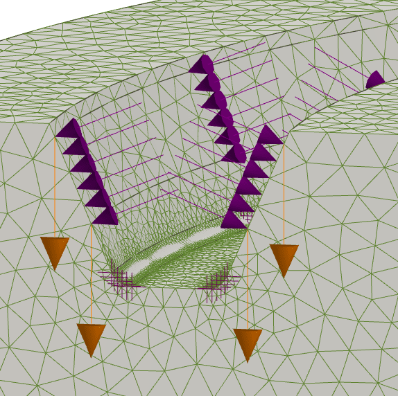
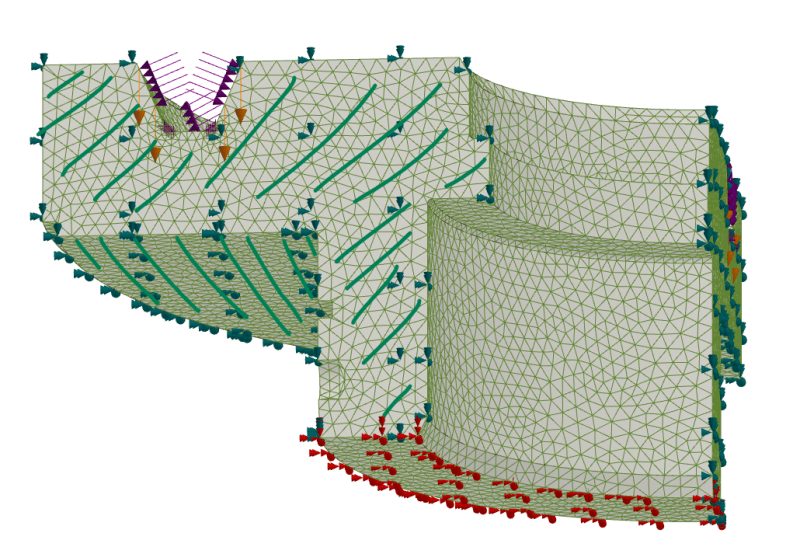
So i'm trying to model the effect of the RTJ Ring on the RTJ groove. I'm using 100% torque value x 2(for safety) x 8 (number of bolts) = force of ring into joint. I modeled the force down onto the 23.5deg angled surface where the ring was hitting and got a stress. Then I thought the program might be modeling the surface of the part being pulled directly inline with the force. I know the force is going to have 2 components, the Normal Force and the Parallel force. I added the normal force as a pressure over the area of effect to mimic a completely normal force. I have not put the parallel force as i think it would pull the surface with a component that would reduce the normal force.

My question is am i overestimating the effect of the ring on the groove by using both the original force and the normal force. Thinking about it i'd say yes i am but i'm kind of at a loss as to a better way to model that. any help would be appreciated.
 
Replies continue below

Recommended for you

Can you add some pictures with your geometry, mesh, loads, constraints and results and show on them what you are doing.

From my experience I remember that modeling O-ring in the flange is nonlihear problem both due material nonlinearities and sliding contact. Do you model your part as nonlinear or as linear? This may give you large error because linear solver is bad at handling even simple sliding contact.
 
Screenshot_2024-03-21_140243-2_fw1vsb.png
Screenshot_2024-03-21_142013_qsmjb2.png


Image is a 1/4 model of a cylindrical piece
The Fy load = the full load generated by 100% torque on the 8 bolts. I'm using inventor 2020 nastran. The load is on the blue surface.
The pressure load is the perpendicular to surface component of the load.
I did not include the load parallel to the surface (pink in close up view), as if i put that load there it would be like 100% friction and i'm unsure of the friction coefficient to estimated the load.
The green sliding surface is contacting a thick steel surface.
The red at the bottom i've set as fixed just to keep the part from spinning off into space. I feel its far enough removed from the action that it should be of little effect. The cylindrical surface between those two surfaces is inside a thick close fitting bore so it won't move tangentially there.
As this is a 1/4th model there is symmetry loads on the symmetry planes.

My main question is, am i overdoing it by including both the Fy and the pressure component. should i include just one or the other? I'm mainly concerned with the material moving too much when clamped to 100%.

I don't do FEA's that often and have not had very much luck AT ALL modeling as assemblies. There is always to many constraints, not enough constraints, the parts appear to slide through themselves even when i set it not too, etc...

I'm not worried about the mesh at the moment as it is more than fine enough to get a reliable result, i'm just wondering if i set it up properly, at least for the most part.
 
Maybe if O-ring is made from some hard material than it if possible to use formulas for wedge, for example from here.
From your pictures P is much lower than Fy but for wedge you should get much bigger P than initial load Fy.

But if O-ring is made from polymer than it becomes even more complex.

Ugh... I can not wrap my head around it.

Definitely if I know mechanical properties of O-ring I would model both flanges parts and o-ring itself in Axisymmetric mode and compress it to obtain both normal pressure and friction force and that use them as load for 3D model.
 
Status
Not open for further replies.
Back
Top