Continue to Site

Eng-Tips is the largest engineering community on the Internet

Intelligent Work Forums for Engineering Professionals

  • Congratulations GregLocock on being selected by the Eng-Tips community for having the most helpful posts in the forums last week. Way to Go!

Modeling tank nozzle in CAESAR II - API 650

Status
Not open for further replies.

allisongibson

Civil/Environmental
Apr 8, 2015
5
Hi, everyone!

I am modeling a piping layout ending at a tank nozzle. I am to check to make sure the tank nozzle loads are under the allowable limit sent to me by vendor. I have all the information to fill in the nozzle flex tab as seen in the snap shot below:
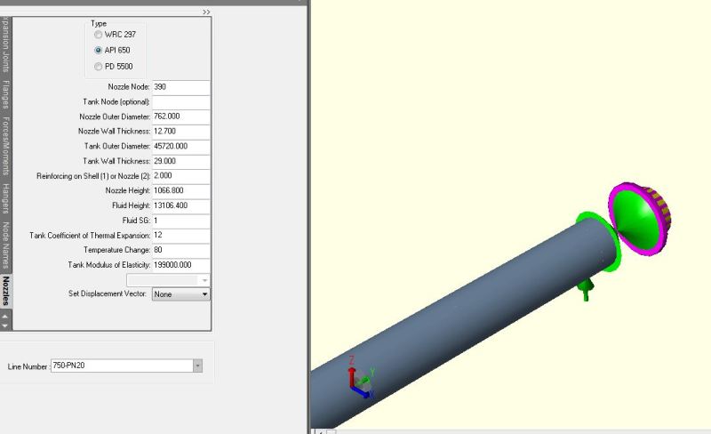
tank_nozzleJPG_njkgyx.jpg


my question is, do I have to model some kind of anchor at the end? Was not sure if the nozzle is considered an anchor or a free end. If not do I need to add a Cnode to act as the tank foundation?
 
Replies continue below

Recommended for you

Is the diameter of the tank you are modelling greater than 36m?
If yes, then click on start run. Read "radial deflection due to fluid& Temp" and Longitudinal rotation due to fluid & Temp" from error and warning page. Again go to input page and dclick displacement. Input two values you had read and tank's edge settlement.
Don't specify anchor at the nozzle point in the tank diameter greater than 36m.
 
BradSmith,

Yes the tank diameter is greater than 36m. So you are saying after I click start run I will use the deflection and rotation from the warning page and apply that deflection to the end of the tank nozzle?

Thanks for your help.
 
Yes, place this values and edge settlement in the displacement table.
 
BradSmith,

When I add the displacement and rotation, do I allow the other directions to move? Or do I set the other directions to 0? Again thank you for your help.
 
You have to add the displacements you have extracted and fill other blank cells with zero.
 
There is a direction vector field D1 to D9 which tells whether the API 650 calculated displacements are to be taken in place of the nozzle node displacements entered. These are explained on the user manual. However it looks to me that the API 650 Tank Shell rotations are not imposed on the node.

It is more realistic to model the nozzle with the API 650 aux menu as it would allow the permitted flexibility of the Tank shell nozzle interface.

I ran this for a 100 m tank for the roof drain connection on the inside of the shell and am not sure whether the rotations are added. With the modelling as Anchor with the displacements and rotations added as vectors the system fails at the nozzle node for overstress, whereas with the API 650 aux, it passes. Rotation of the shell is detrimental than the radial displacement from the liquid head.
 
Status
Not open for further replies.

Part and Inventory Search

Sponsor