Continue to Site

Eng-Tips is the largest engineering community on the Internet

Intelligent Work Forums for Engineering Professionals

  • Congratulations SDETERS on being selected by the Eng-Tips community for having the most helpful posts in the forums last week. Way to Go!

Modelling pressurized cylinder 1

Status
Not open for further replies.

sushi75

New member
Mar 11, 2015
84
Hello everyone,

I try to model a cylinder of internal radius a and external one b. The structure is submitted to a radial pressure p. The cylinder is opened on both ends.

From books, there is a radial and hoop stresses, but the z-stress is equal to zero. I don't understand this point as I expected from Poisson ratio that there will be a stress on the z direction. I guess it is related to the open ends, but I cannot really understand this point.

So to convince myself, I would like to run a FE model, but the problem I have is that there should not be a boundary condition to constraint the translation on the z direction as both ends are opened, but if the model doesn't have it, then there will be a rigid body mode.

So how can I have a model that truly represents this open pressurized cylinder without getting an error message?

Thanks for all the help you can provide me!

 
Replies continue below

Recommended for you

in a thin shell barrel there'd be no significant stress in the radial direction (the "z" direction) as the thin shell isn't considered to be strong enough to resist the deformation. The shell wold be microscopically thinner.

in a thick shell barrel the shell is thick enough that the central fibers would feel a radial, or z, direction stress.

another day in paradise, or is paradise one day closer ?
 
i think you have a bigger problem is you model an open barrel, in that you won't see the axial/longitudinal stresses (from the end caps).

but maybe you just trying out something, just to see. ok, but what error are you anticipating ?

it is easy to model a circular shell (2D plate elements). and load with pressure. ensure that you add rigid body constraints (3-2-1 on 3 nodes on one end). then you should see the barrel deflect as it should.

another day in paradise, or is paradise one day closer ?
 
You need to review some "strength of materials" things.

1) Poisson 's ratio has nothing to do with stresses. Only with strains. Poisson 's ratio does not produce stresses. An axial load does not produce plane stress conditions due to poisson 's ratio.
2) A thin thick tube with open ends and radial pressure, has only radial stress.
3) You can add nearly zero stiffness springs as contsraints.
 
in reference to Blas's post ... I would not recommend modelling 1/4 circular arc of the fuselage (if that's what Blas meant) ... maybe it can work but these days is there much to be gained (employing symmetry strategies) ?

another day in paradise, or is paradise one day closer ?
 
In addition to what Jacksonfem & RB1957 has posted, stresses are only produced if there is resistance to deformation. If the component is free to deform, strains are produced but no resistance and hence no stress. In a thin pressurized cylinder, the wall thickness is very small and hence it would easily deform in the radial direction (think of surface of a balloon which expands freely as you pump in air) and hence no radial stresses. That is why in thin walled cylinders, the state of stress is said to be Plane Stress.

Further, you would not have any longitudinal stresses in the cylinder as well if the end caps are no present. Again the cylinder is free to deform (or extend) in longitudinal direction.
 
Thanks for all the tips you provided.

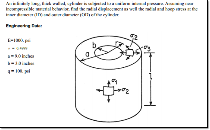
Ultimately, the goal of this model is to understand why Sigma_1=0 (see attached picture).

I cannot really understand why based on engineering judgment; so I try to convince myself with FE analysis.

I also tried to prove that with the equilibrium equation, div(sigma)+f=0, but again I could not manage to prove this result...

Does anybody have managed to do so?

Many thanks!
 
 http://files.engineering.com/getfile.aspx?folder=8d6428b0-1784-4747-8a14-637542fee761&file=problem.png
because there is no stress in the longitudinal direction in a cylinder (without endcaps) under pressure. there is no poisson effect as the shell expands (as notes above, like a balloon),

another day in paradise, or is paradise one day closer ?
 
Dear sushi75,
A picture is better than 1000 words, good!.

cylinder-long-thick-walled_rk7ujf.png


You can solve this problem on FEMAP with NX NASTRAN in say three ways, arriving to similar stress & displacements results. This is true because the cylinder is thick walled and LONG, then the "boundary" effect should be neglected:

1.- 2-D Solid Axisymmetric Analysis:
Axisymmetry occurs when a geometric part is a body of revolution and the loads and constraints acting on the part are only radial and axial, that is, they are cylindrical, with no tangential component. Axisymmetric modeling is useful for body of revolution parts such as pressure vessels. The model is built on an axisymmetric plane X-Z, and rotates around the rotational Z-axis.
Axisymmetric analysis requires you to properly align the center of rotation and the radial axis of the axisymmetric model to the absolute coordinate system. For example, in the NX Nastran environment the center of rotation is the absolute Z-axis, and the axisymmetric plane is absolute XZ. The model must lie in the +X half of the XZ plane (X is the radial direction, and Z is the axial direction).

In NX NASTRAN the axisymmetric elements CQUADX4 define a solid ring by sweeping a surface defined on a plane through a circular arc.
You can request that NX Nastran output the following stresses, which it evaluates at the three vertex grid points and the element’s centroid:

• σr – stress in rm direction of material coordinate system.
• σθ – stress in azimuthal direction.
• σz – stress in zm direction of material coordinate system.
• τrz – shear stress in material coordinate system.
• Maximum principal stress.
• Maximum shear stress.
• von Mises equivalent or octahedral shear stress.

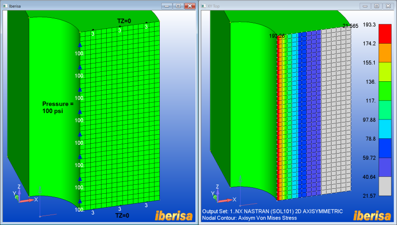
Here you are the 2-D mesh + loads & BCs, together with vonMises nodal stress results:

axisymmetric-model_gsxskt.png


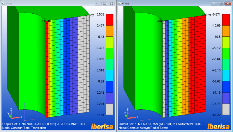
Next here you are the resulting displacements + axial nodal stress:

axisymmetric-results1_psdtzf.png


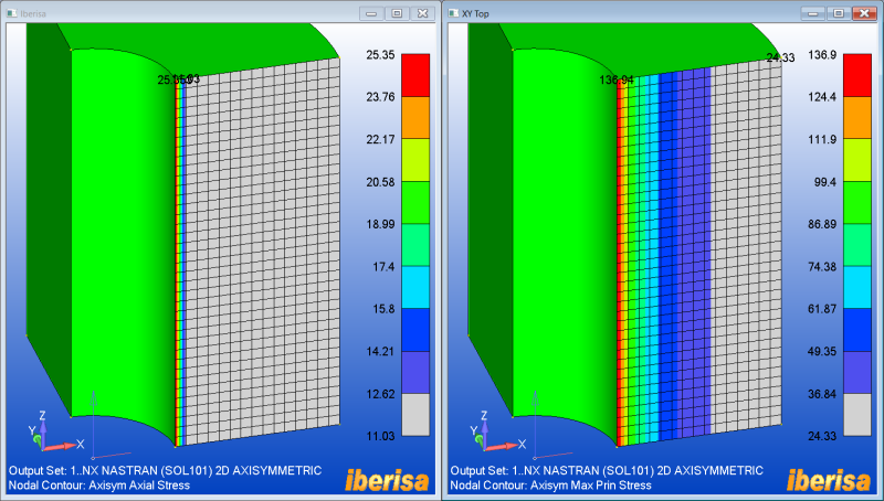
And finally the Axial nodal stress + the maximum nodal principal Stresses:

axisymmetric-results2_cxvxhm.png


2.- 2-D SOLID PLAIN STRAIN ANALYSIS
Plane strain elements are two-dimensional elements with membrane only stiffness and in-plane loading. The plane strain element idealization has zero strain in the thickness direction. These elements represent structures that are very thick relative to their lateral dimensions. This is the case of the THICK walled cylinder.

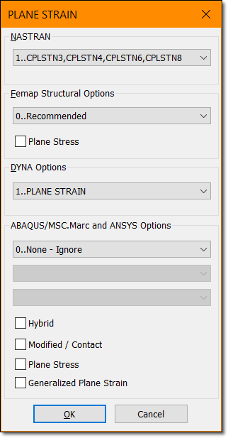
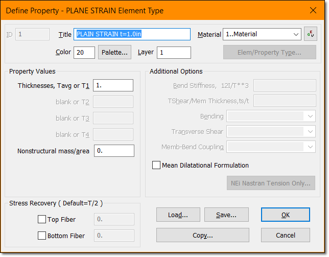
The element used here is the CPLSTN4 4-nodes 2-D solid plain strain element. Please remember to activate the plain strain formulation when selecting in FEMAP the plane strain property: simply use a unitary value for the element thickness:

◦ They must be defined in the X-Y plane of the basic coordinate system.
◦ All loads must be in-plane. The PLOADE1 entry can be used to define edge loads.

plane-strain-formulation_rxuplj.png
plane-strain-property_nys6y3.png


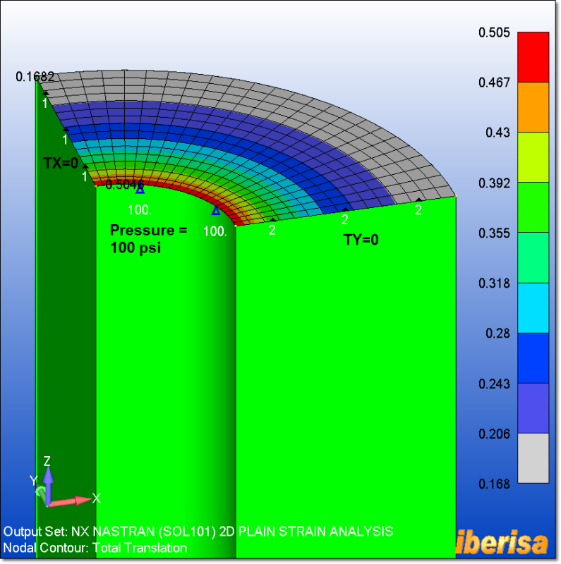
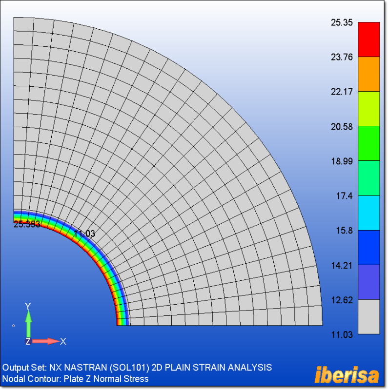
The following picture shows the loads & BCs imposed to the 2-D plain strain model, together with the displacement resaults: you can study any unitary cross section along the cylynder, bacause the cylinder is INFINITELY LONG the result is basically the same, OK?. Then your 2-D meshing approach is capturing perfectly your 3-D Solid problem.

plane-strain-URES_ft7eb4.png


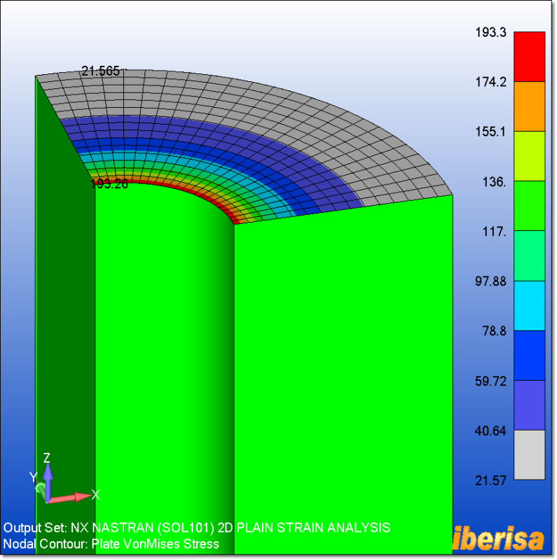
Here you are the vonMises nodal stress of the model, exactly the same value as the axisymmetric analysis.

plane-strain-nodal-vmises_bx17pf.png


The Plane Strain z-normal nodal stress is exactly the same as the Axisymmetric Axial Stress:

plane-strain-znormal-stress_bubpqn.png


3.- 3-D SOLID CHEXA ELEMENTS
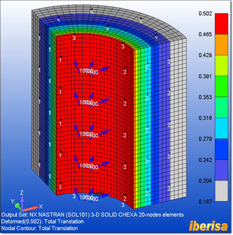
And finally the problem is solved using 3-D solid CHEXA 20-nodes elements, taking in consideration 1/4 of model because we have symmetry of both loads & geometry, in spite of others say the contrary!. Taking advantage of Symmetry BCs is critical, allows you to stabilize the model and arrive to a fast & reliable solution.

cylinder-3d-solid-ures_vz9r4z.png


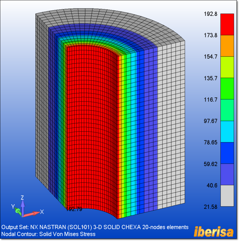
The following plot shows the nodal vonMISES stress, with results at the level of the previous analysis. To increase accuracy simply you need to get rid of boundary effect prescribed at both ends: expand the model in the longitudinal direction and the influence of the BCs prescribed at both ends will be negligible.

cylinder-3d-solid-nodal-vonmises-stress_qy4h3u.png


Best regards,
Blas.

~~~~~~~~~~~~~~~~~~~~~~
Blas Molero Hidalgo
Ingeniero Industrial
Director

IBERISA
48004 BILBAO (SPAIN)
WEB: Blog de FEMAP & NX Nastran:
 
Hi Blas,

Thanks a lot for this very detailed answer which is very helpful. Again the information you provided is gold mine!

I understand the different way of modelling the problem, and the fact that the cylinder length is infinite is the key.

So for my understanding, what if the length was not considered as infinite? Would we get a sigma z stress in that case?

To follow rb1957 's comment, yes I think I got confused with Poisson ratio and stresses. It's only related to strain. But on the same time strain and stresses are also related with Hookes law. So it's a bit misleading somehow.

What I try to do is to get a general idea of what a stress distribution could be like prior to run an analysis. Maybe it will be easier if I consider a flow analogy (fluid mechanics) for stresses?

Thanks!
 
Dear Sushi75,
In the case of a thin cylinder, then the problem can be solved as 2-D solid PLANE STRESS in the X-Y plane using NX NASTRAN CPLSTS4 4-nodes elements.
Plane stress elements are two-dimensional elements with membrane only stiffness and in-plane loading. The plane stress element idealization has zero stress in the thickness direction, but the STRAIN is not zero in the thickness direction, here is governed by the Poisson ratio. These elements represent structures that are thin relative to their lateral dimensions and planar, for instance in the case of the cylinder where the inner diameter is 3.0 thin means a thickness of say 0.3 mm.

Best regards,
Blas.

~~~~~~~~~~~~~~~~~~~~~~
Blas Molero Hidalgo
Ingeniero Industrial
Director

IBERISA
48004 BILBAO (SPAIN)
WEB: Blog de FEMAP & NX Nastran:
 
Hi Blas,

Again, many thanks for your continuous support. It's becoming clearer and clearer!

I think the wrong concept/vision I had (maybe a common one?? :) ) is that any strain is resulting from a stress in the same direction.
The example of the plane stress element you mentioned is a good counter example: there is a strain in the z direction without any stress in this direction.

I guess this is something that in a way misled my 'engineering judgment'...
 
Please note "thin" cylinder means a small value in the Z-axis direcction, ie, the height "L" of the cylinder according your drawing, not the wall thickness, this way we are assuming a cyliner disk of small thickness, OK?. In this case is clear that if not load exist in the Z-axis direcction, then not stress exist at all, but strain Epsilon-Z is not zero.

Best regards,
Blas.

~~~~~~~~~~~~~~~~~~~~~~
Blas Molero Hidalgo
Ingeniero Industrial
Director

IBERISA
48004 BILBAO (SPAIN)
WEB: Blog de FEMAP & NX Nastran:
 
Status
Not open for further replies.

Part and Inventory Search

Sponsor