Good day, colleagues.
I am doing the verification calculation of the building and I have a question: how to correctly design the following slab. Let's take the slab segment around the core of the building.
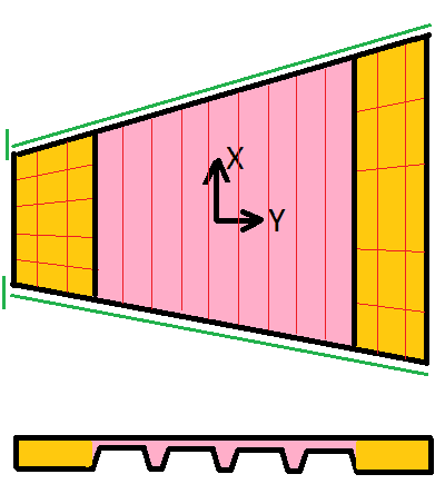
We have a monolithic segment, then there is filled deck, then near the facade again a monolithic segment (pic 1). It all is supported by cantilever beams that come from the core.
The question is how to properly design such a combined slab in SAP2000? As I understand, the monolithic segments should be modeled by SLAB-THIN type, with appropriate coefficients of cracking, but how to model the segment of filled deck?
With a membrane - without creating a mesh and without considering the stiffness of the rib? But then how to relate the work at the slab in the Y direction to the monolithic segments if there is no mesh?
By slab - and lower to 0.001 the bending and shearing stiffness in the Y direction, and in the X direction calculate the real stiffness of the "beam" as a section "T" (pic 2)? Wouldn't such a model have inflated stiffnesses?
Can you tell me how you model and calculate such slabs with such sections?

For reference:
Picture 1: orange - monolithic slab, pink - filled deck, green - beams, red lines - mesh as I see it if I model the filled deck as a membrane.
Picture 2: M11 - section of the filled deck across the span to calculate the stiffness of M11 and V13, where the width of this section is equal to the spacing of the ribs; M22 - section of the slab along the span by 1 unit length, thickness equal to the thickness of the slab above the deck, needed to calculate the stiffness of M12 and V23; M12 - same as for M22, needed to calculate the stiffness of M12 and V12 in the slab plane, thickness the same as for M22.

I am doing the verification calculation of the building and I have a question: how to correctly design the following slab. Let's take the slab segment around the core of the building.
We have a monolithic segment, then there is filled deck, then near the facade again a monolithic segment (pic 1). It all is supported by cantilever beams that come from the core.
The question is how to properly design such a combined slab in SAP2000? As I understand, the monolithic segments should be modeled by SLAB-THIN type, with appropriate coefficients of cracking, but how to model the segment of filled deck?
With a membrane - without creating a mesh and without considering the stiffness of the rib? But then how to relate the work at the slab in the Y direction to the monolithic segments if there is no mesh?
By slab - and lower to 0.001 the bending and shearing stiffness in the Y direction, and in the X direction calculate the real stiffness of the "beam" as a section "T" (pic 2)? Wouldn't such a model have inflated stiffnesses?
Can you tell me how you model and calculate such slabs with such sections?

For reference:
Picture 1: orange - monolithic slab, pink - filled deck, green - beams, red lines - mesh as I see it if I model the filled deck as a membrane.
Picture 2: M11 - section of the filled deck across the span to calculate the stiffness of M11 and V13, where the width of this section is equal to the spacing of the ribs; M22 - section of the slab along the span by 1 unit length, thickness equal to the thickness of the slab above the deck, needed to calculate the stiffness of M12 and V23; M12 - same as for M22, needed to calculate the stiffness of M12 and V12 in the slab plane, thickness the same as for M22.

