Eng-Tips is the largest engineering community on the Internet

Intelligent Work Forums for Engineering Professionals

Modelling the Slope in Geostress with Dynamic Explicit in Abaqus

Status
Not open for further replies.

SKSA

Civil/Environmental
Feb 28, 2024
27
0
0
CA
Hi,
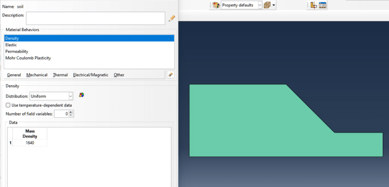
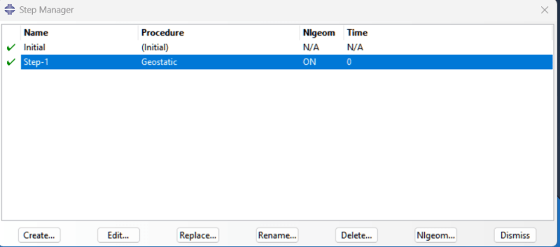
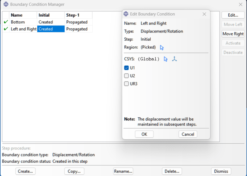
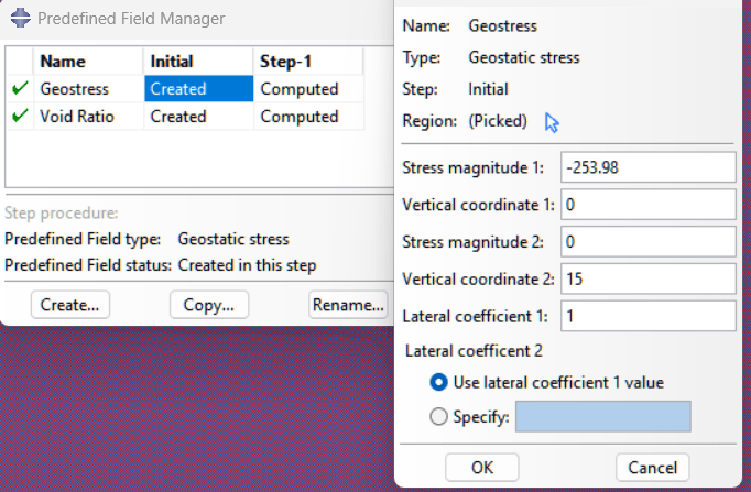
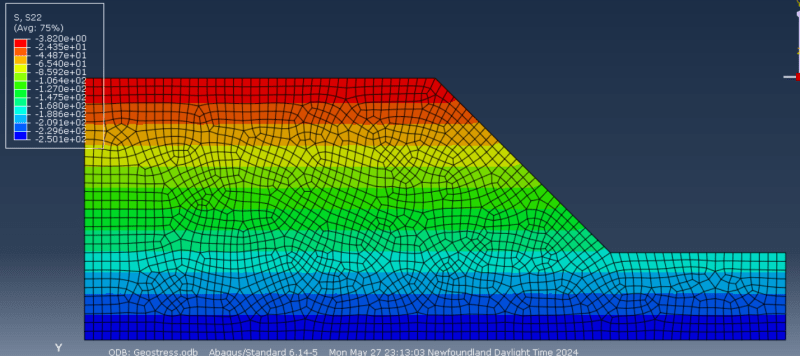
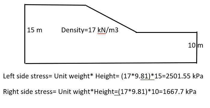
I want to model this slope in Geostress condition where I will expect this kind of result after end of the step. I can apply predefined field in the slope. I want to run this analysis in Dynamic Explicit Mode. But after running this analysis , I am not getting the expected result as this figure shown. Rather it shows the same stress at the bottom where I would expect less stress in right side because height is smaller than left side. Can you please guide me how can I overcome this type of problems?
Slope_fkizti.png
 
Replies continue below

Recommended for you

I tried that one too. It shows the same stress in both side. But I would expect different stress according to theory.
 
Actually, why do you need Explicit in this case ?

Can you share the model or at least describe all the boundary conditions, loads, interactions and other important setup details ?
 
Hello Sir,
Thank you so much for your prompt reply. Actually, my second step will be dynamic as I wrote the Modified Mohr-Coulomb VUSDFLD Subroutine for Dynamic analysis. I want to see that my slope is stable in the first step, and in my second step, I will apply the MMC where the slope might fail. So I am facing the problem in my first step. In dynamic analysis, it shows higher kinetic energy. And as per your direction I tried in standard. But I am not sure what could be the problem in my modeling. I am describing the modeling properties for your better understanding. Please give me some valuable suggestions to overcome my problem.
1. Here is my geometry and property. Left side is 15 m height and right side is 10 m.
Geometry_and_Property_grahff.png


2. Here is the first step. I used the Geostatic Step.
Step_v40sxm.png


3. Here is the Boundary conditions. In my case, the bottom is restricted in an upward direction. The left and right sides are restricted by horizontal direction.
Boundary_Condition_ldy4xg.png

4. I used a predefined field to define the initial stress of the slope and the void ratio.
Predefined_Field_plfukn.png


5. Here is the resulting photo where the stress is the same at the bottom when the time is equal to zero. And after finishing the geostatic step, it shows very different results, which is not acceptable according to theory.
Results_t6oeiy.png

Can you please have a look at it and give me some suggestions from your busiest time? I am also attaching the Abaqus CAE file for your better understanding.


Why don't you have a gravity load in this model ?

Regarding the explicit dynamics analysis, my question is why you need it instead of a static, quasi-static or even dynamic analysis using the implicit solver (Abaqus/Standard) with USDFLD subroutine (instead of VUSDFLD).
 
I can use gravity loading. But if I want to use different earth pressure coefficient then how can I do it? Is there any other way to define it?
 
Status
Not open for further replies.
Back
Top