Continue to Site

Eng-Tips is the largest engineering community on the Internet

Intelligent Work Forums for Engineering Professionals

  • Congratulations waross on being selected by the Eng-Tips community for having the most helpful posts in the forums last week. Way to Go!

Modifying End Wall of Existing Private Residence 3

Status
Not open for further replies.

Enable

Structural
Jan 15, 2021
760
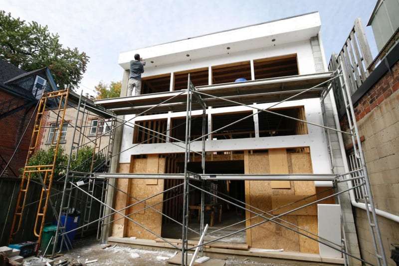
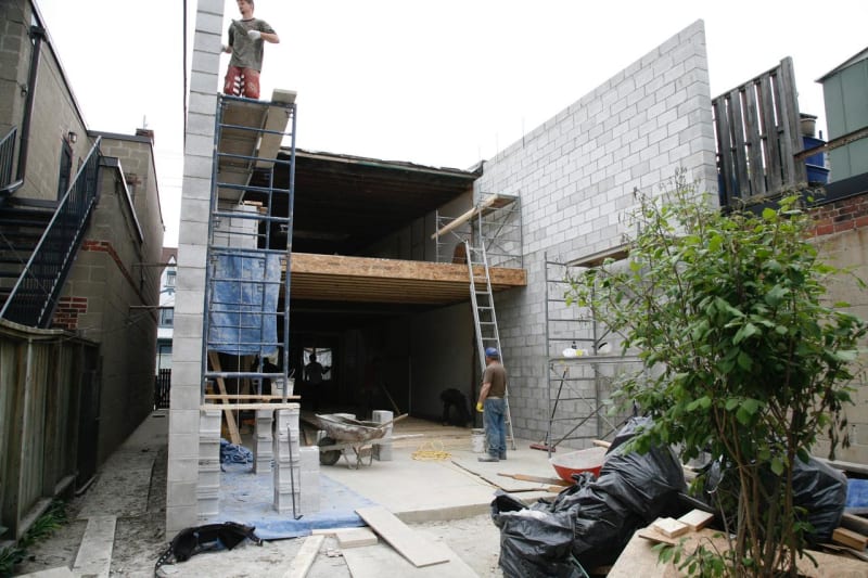
I am looking at an existing two-story residence in a low seismic area where the owner has previously added a CMU enclosed addition with a wood / window end wall (see pictures). But now wants to remove the end wall and place a full height curtain wall in its stead.

My concerns are

A) Lateral stability of the CMU wall ends
B) Getting the roof diagram shear forces down to grade
C) Deflection of the CMU wall ends and tolerances of the curtain wall for such deflection
D) Don’t want to rely on the curtain wall for lateral stability or load transference though it will have some capacity

Unknowns are

A) Is CMU reinforced (to be confirmed via scanning)
B) Joist to CMU connection at roof (to be confirmed via openings)
C) Layout of interior and end shear wall (to be confirmed via site visit)
D) Everything else

Access to

A) Permitted Drawings (unfortunately…almost no structural details…have no idea how it passed review). Doesn't even say if CMU is reinforced or not.

Options

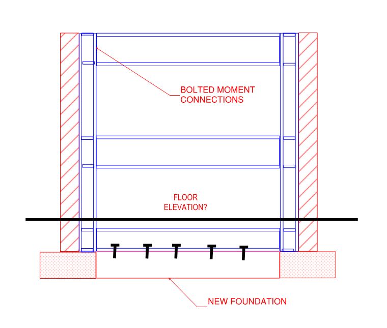
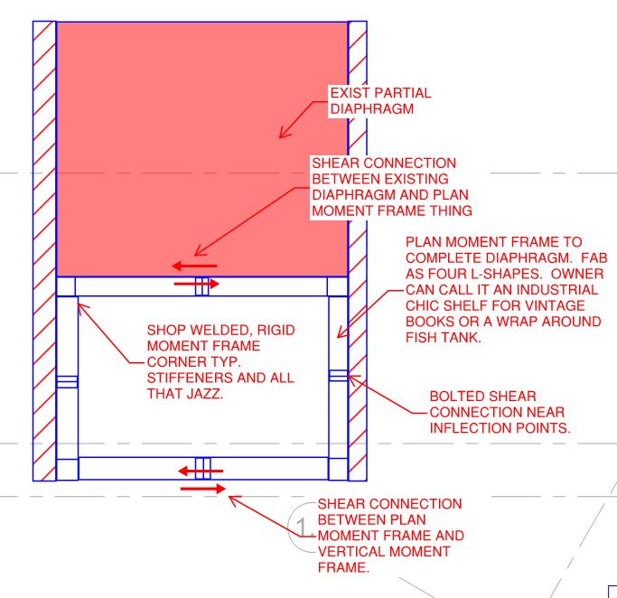
Portal Frame: I could create a portal frame out of steel members to enclose the curtain wall. I’d connect top flange of the portal directly to the deck sheathing. Probably welded moment connection between posts / beam. Carry posts to some footing structure below grade. And bolt the flanges to the existing CMU vertical walls.

Stabilizing Beam: If the existing design, which really does not have a lot of stiffness to it (I don’t really buy that the window framing may act as a deep beam and hence provide a great deal of stiffness…though maybe it is, I don't have an attuned feel for wood construction), we should be able to get away with just restoring the lateral stability to top of the CMU wall. This can be accomplished by a simple spanning beam from CMU wall to CMU wall that I would weld to embedding plates. Basically, the portal frame idea sans posts.

Other Options: Provided by you!!

Notes

If I can get away with just a beam at the top, I’d love it because it’s way cheaper / easier and I won’t have to deal with that CMU wall as it looks like it’s 3” out of plumb (which will be an issue for my portal).

If I go with a portal, I’d have a stiffness mismatch between the portal and the wood shear walls on the other side of the building. Once I verify their construction, I’ll attempt an iterative rigidity analysis to equilibrate the deflections (as much as I can).

Loads are mostly just wind and are quite low so maybe it is all moot and anything will work.

Thoughts?
mail1_l8rzfs.jpg

mail1_1_wahmrk.jpg
 
Replies continue below

Recommended for you

1) I like the steel portal frame and suspect that most engineers would want to go that route.

2) Top beam without steel columns setup doesn't make sense to me. You'd have to call the block walls your sway columns and moment connect them to the beam somehow. That messy, difficult to assess, and lacking precedent as far as I know.

Other options:

3) Are there any interior shear walls that might be available to you, even if you have to turn them into steel braced frames?

4) Is there any lateral attachment to the existing building that exists or could be created to stabilize the addition?

Enable said:
If I go with a portal, I’d have a stiffness mismatch between the portal and the wood shear walls on the other side of the building.

5) I'd not worry about that much with a steel deck diaphragm of that aspect ratio. If you're feeling fancy, maybe design the moment frame for 50% of the wind shear and the back wall for 65% of the wind shear.

Enable said:
Loads are mostly just wind and are quite low so maybe it is all moot and anything will work.

6) I wouldn't be quite so cavalier. A large part of your stability issue here is the weight of those heavy block walls tending to rack the building in P-Delta failure. The wind may just be the thing that sets that catastrophe in motion. And nobody likes getting pancaked by a giant block wall...
 
Well that's pretty nifty. If I had to guess, I'd say there's either a portal frame of some sort wrapped on the edges there already OR the architect ignored lateral force resistance...wouldn't be the first time! I had to deal with a vaguely similar issue (if you squint and look the other way, it looks identical) where an addition done 20 years ago ripped down the rear braced wall, extended the house 40 feet, and the only wall put up to 'replace' the braced walls was 98% glass with no steel in it. It's waterfront, on the bay, with a solid 90 mile fetch over open water. The owner didn't like what I had to say, so she fired me.

I'd do a portal frame in this - especially if they want a full wall of glass curtain wall. I wouldn't worry much about the equalizing the deflection between the wood shear walls and the portal. You'll probably never get there, and it won't matter much anyway. If seismic isn't a concern, then just make sure it's strong enough to take the wind loads and stiff enough to give you manageable deflection at a 10 year MRI. This assumes there's nothing special about the house that would make it split in half if the differential deflection exceeded some value. Haven't seen that myself, but I suppose it's possible.

 
Thanks gentlemen. I was hoping both of you would take a gander!

KootK: Great alternative options. Unfortunately, no lateral support is existing from neighboring buildings, and I would not want to rely on anything newly installed for this purpose. Also, nothing on the interior ties back to the original build in a satisfactory way to restrain lateral movements as far as I can tell. The nearest cross-building wall is at the very start of the addition and I feel that still leaves us much too far from the end for comfort in terms of stability of the CMU.

BTW I was looking for some confederates to come onboard with a simple, though somewhat wanting solution as it would be a much easier sell. Alas, no one could be swayed [pun intended]

phamENG: The existing end might be acting as a portal of sorts but based on conversations with the GC there was no structural steel used on the addition. So, if there is a portal behind the box-outs, it is entirely wood constructed and I’m not sure I’d trust the detailing of it all to actually constitute a moment frame. Also, I fabricate and sell steel so that sounds like a great option lol!

Thanks for bringing differential deflections to my attention; I’m not sure I would have thought about splitting the building in half in this instance but certainly a good thing to at least review. Very much appreciated

Further Questions

A) I’ll confirm the allowable deflection with the curtainwall supplier but for preliminary purposes do you have any feel for deflection tolerances? This glass magazine bulletin seems to suggest H/240 as a minimum (19mm max total). Seems a bit high though so I may shoot for a more typical H/480. I've seen some varying responses I’ve on eng-tips as well. Any experience with such deflection criteria?

B) For the connection from the portal columns (assumed W-section) to the CMU I was intending to bolt through the flange at every other course. Anchor size and exact spacing to be determined based on loads, obviously. But I am thinking to use this for my preliminary spacing because it’s similar to a header course every 6 courses of brick (~16 to 24” c/c) and will engage enough CMU units that I don’t need to worry too much about failure planes between them (so long as it’s grouted / reinforced). Any thoughts on this?

C) For my footing I intend to construct one at the same elevation as the footing for the adjacent CMU (assuming it meets for frost) and try to create a more-or-less monolithic connection via doweling. For windward moments the force would be resolved via bearing of the footing extension on the interior side, and by shear transference to the dowels on the exterior side that gets resisted by the CMU weight. For leeward moments the moment would be resolved simply by the mass of the footing on the interior side. I plan to proportion the footing as if the portal frame takes the entirety on the load though realistically the CMU will contribute something. Anything I am missing with the load path or things that I will be affected but have not considered?

EDIT - KootK i've only edited this 7 times so at least I am improving [lol]
 
Enable said:
Thanks gentlemen. I was hoping both of you would take a gander!

You are our current Tip Master of the Week after all. It would be an embarrassment if we couldn't take care of your questions. Plus you're Canadian...

A) Yeah, h/500 would be my starting point.

B) I'd open up the connection spacing to something more like 48" oc. You're important connection here will be between your roof deck and the top of the portal frame. You really only need the wall connections to iron out differential wind deflection and, perhaps, provide frame uplift resistance. 48" oc should be plenty for those purposes.

C) Per the sketch below, this might be a good application for a system that our European cohorts favor. If you're going to go with discrete pad footings and no low beam, I'd do this:

a) Chip away the existing wall footing adjacent to the new pads.

b) Case in the new pads dowelled to what's left of the old footings.

c) Call your bases either pinned or only fixed for closing moments. I think that opening moments might cause you trouble with:

i) the limited DL that you'll have to resist OT and or;

ii) detailing moment transfer at the joint for opening moment.

C01_t4yoyz.jpg
 
Enable said:
This glass magazine bulletin seems to suggest H/240 as a minimum (19mm max total)

That value speaks to deflection perpendicular to the plane of the wall. Racking's what you're interested in and, as you've rightly assumed, will be more stringent.

Enable said:
EDIT - KootK i've only edited this 7 times so at least I am improving lol

Forget my previous assholery. I was tired and dodging real work. I edit my posts all of the time. In fact, somewhat in violation of forum policy, I do this:

1) Slap something down as a draft.

2) Return to some real work for a while.

3) Return for a spell check and some additional thoughts.

I never have time to do it all in one go and, if I don't save the draft, I wind up closing the Chrome tab and losing what I wrote.
 
KootK said:
European Option

I'm always in favour of stealing from our European brethren. I recently incorporated a predominantly European move into my arsenal as a tendy and my beer league game has never been better! Bet you a timbit only Canadians will understand that last sentence

I like this configuration. The statics of overturning and such are similar so it doesn't change much in terms of mass of concrete needed in the footing (EDIT - this is true if designed independent of existing. But I suppose if the footing is reinforced to act as a single rigid body one might comfortably rely on shear dowels to engage adjacent CMU without having to develop a moment connection and that WOULD reduce concrete required in the new footing). But regardless it does simplify the connection to the footing (i.e. makes it easier to distribute loads into center of footing mass). Would you agree that the bottom beam primarily acts as a load distribution mechanism to the footing or do you see another advantage (it obviously acts as a tension tie in gravity loading but to me that would just be bonus)?

KootK said:
Re: concrete mass

BTW I know engineers are sometimes worried about concrete costs and such but for things like these they need not be. Especially when the difference is between half a truck and a full truck or something near that. As a contractor the minimum charge to get a truck + underload charges (we get charged /m3 not on the truck under full capacity) leads to the following (Enable) rules of thumb regarding ordering:

If you've bought 1m3 of good concrete (e.g. 35 MPa C1/C2) then you've bought 3m3 (also 3m3 is min for testing per CSA anyways)
If you've bought 1m3 of shitty concrete (e.g. residential 25 MPa) then you've bought 6m3

I generally don't mind if a design needs a little more concrete. Though I do try to keep it such that an incremental truck isn't needed for such a marginal amount (e.g. if a design would need 9.5m3 I try to re-work it to 9m3 or ideally a bit less).

KootK said:
Forget my previous assholery. I was tired

All is well. I am also quite tired so that no doubt added to it. My brother has been away for nearly 3 weeks to take care of his newborn, and it has left me trying to manage a construction division, a fabrication shop, and a design side and I am really starting to feel the pain. He is a huge help (he's our resident CWB engineer + site super) but I am happy we have the ability to let him spend time with his family. But I am dying over here and hope he comes back soon.

So that is to say: I'm sorry as well. I probably wasn't communicating nearly as well as I could have due to being tired and yeah. I have continued to follow your discussion with Steve though. I dare say he seems to have convinced you of some of the things I was attempting (poorly) to say ha!
 
Enable said:
overturning and such are similar so it doesn't change much in terms of mass of concrete needed in the footing (EDIT - this is true if designed independent of existing. But I suppose if the footing is reinforced to be rigid one might comfortably rely on shear dowels to engage adjacent CMU without having to develop a moment connection and that WOULD reduce concrete required in the new footing).

Oh yeah, I would definitely try to engage the mass of the wall via the wall/column connections to resist overturning.

Enable said:
. Would you agree that the bottom beam primarily acts as a load distribution mechanism to the footing or do you see another advantage (it obviously acts as a tension tie in gravity loading but to me that would just be bonus)?

Meh, I see the bottom beam as really:

1) Being effective as a distribution element for shear only.

2) Primarily a way to get some measure of fixity in your base columns whiteout attempting painful moment connections to the foundations. Depending on your starting point with your moment frame, it can be somewhat like getting two moment frames in one in terms of stiffness.

Enable said:
BTW I know engineers are sometimes worried about concrete costs and such but for things like these they need not be.

It's a nuanced thing. Concrete can be cheap in these contexts but, often, more concrete also means more rebar and more excavation. And those things can add up.

Enable said:
I dare say he seems to have convinced you of some of the things I was attempting (poorly) to say ha!

The tally according to me.

1) I gave up my loose hypothesis that the U-factor might be offering intentional protection against hinge development.

2) I came to suspect that it is strain hardening and the secant modulus aspect of the shanley column concept that is the best bet for protection against hinge development. Those things were known to be beforehand. My shift in thinking was really in abandoning the idea that protection against hinge development existed within the interaction equation itself. It seems that it does not which, naturally, sends us off in search of these "other things" which are difficult to quantify and for which we can only speculate at the code writers' intent.

3) I came to better understand the nature of the 0.85 factor and the interaction equation as a whole.

4) It seems pretty clear to me now that your hypothesis that Cf/Cr was offering protection is incorrect. The addition of terms in the interaction equation seems to produce a completely plastic cross section per our better understanding of the 0.85 factor.

5) I still contend that attempts to monkey with the reliability setup of the code are inappropriate.

6) One of your diagrams did, very loosely, hint at the importance of strain hardening and localized plasticity in the context of the Shanley column concept.


I would favor a moment frame. Bet they're not going like the depth of members needed to resist drift!

One confounding issue:
I sometimes am asked to design a new house (with a great view) right next to an all brick building that has the rear wall removed. The client wonders why THEY need a moment frame when there is and unreinforced brick building doing perfectly fine right next door!

About the deflection limits:
I find newer large opening window/door systems have VERY TIGHT deflection limits (like L/600 AND 1/4" max for vertical deflection). There is not much appreciation for drift limits but I tend to aim for very tight limits (L/360 or better). I see other buildings going up where they clearly are not looking at drift limits but use 4" steel columns and 8" beams having simple connections and they pretend that is a moment frame.

An interesting experience (to me anyway) I was speaking to a former colleague who moved to California (I'm in the Midwest US) and he was showing me some of his recent projects - modern homes with large glass openings. Drift was resisted by 5" steel columns (basically a series of masts) having moment bases. I asked him what the drift was and he said 4" !! I guess seismic design is not for continued use but rather, life safety. Still, that seemed like a lot.
 
HouseBoy said:
I guess seismic design is not for continued use but rather, life safety. Still, that seemed like a lot.

That sounds questionable. Certainly, on multistory buildings one needs to concern themselves with the glass falling out and:

1) Hurting whomever it lands on and;

2) No longer acting as a guard rail of sorts for folks inside.
 
Hey team,

The portal frame is a go. Hurray! Also, some results are in.

Roof openings have confirmed that the joist detail is a ledger anchored at 48 c/c to the CMU with (presumably) J-hooks and joists toe-nailed into the ledger. 10” thick CMU. CMU is reinforced at the bottom 4-6 feet or so along the length and then at the ends of the wall. The CMU is unreinforced in the middle / bulk of the wall.

Scan below (done by xRadar who I recommend to anyone. Absolutely love them)
Bar_Layout_zbdisf.jpg


However, I do have a question with regards to the CMU layout based on the scan. To preface this convo: I have very little experience with unreinforced CMU, and at the moment my office Masonry Code is with my brother (I’m extricating it tomorrow to see what I can glean).

The CMU wall is laterally unbraced for the most part. The middle floor starts 14’ back from the exterior wall to be replaced but this just provides a pinned joist connection. The nearest perpendicular, sheathed wall, is 40 feet back into the building.

I am unsure how to feel about this. I can restore lateral support at the portal without issue but the existing construction seems a bit lackluster. This document from the Canadian Concrete Masonry Producers Association suggests that empirically lateral support would need to be provided at a H/T ratio of 20 ~ 17 feet in this case. The building is approx 25 feet in height and as I mentioned, the nearest true lateral support inside the building is 40 feet from the portal.

Interior of the building is finished to the 9s and any invasive work would be quickly condemned. So, I am wondering the following:

A) How do these spans feel from an experience perspective for unreinforced CMU? Like I said, I have little and Drysdale (author of document above) is the Canadian go-to when it comes to masonry and the limits he suggests are not observed in this case.

B) If the lateral support is wanting what does one suggest if interior work is frowned upon?
 
You should be able to squeeze enough strength out of it to show it works. I just ran a quick check of a 14' long, 25' tall URM wall (10" thick nominal, 1500psi f'm) with 15' feet of roof trib (15psf dead, 20psf live, 40psf snow) and a wind pressure of 18psf and it works without issue. This is using US codes and I'm not sure what your design wind and snow loads are going to be, but I think there's hope.
 
Thanks phamENG. Good to know the proportions we are looking at are not that far out of the norm.

That said, taking a walk through our masonry code leads me to believe that the wall fails a tensile resistance check when considering it a spanning element from grade to the roof. I imagine there might be a way to take into account arching of the compression face to increase wall capacity but I didn't see it in our code (though I am a newbie when it comes to CMU). Are there other checks than tensile resistance that might allow this wall to fly?

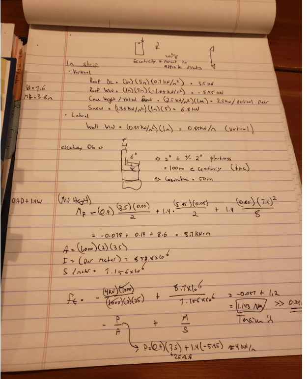
BTW: Below are my calcs (A/S values for 240mm CMU per CCMPA). Perhaps you could take a look and tell me where I've gone wrong (I assume I must have given you said your quickie checked out)? One thing I included that you may not have was the fact that the wind uplift on the roof counteracts the roof DL, and given the eccentricity on the wall, this enhances the bending moment. You'll note that I neglected the amplification factors because this would only make matters worse.

EDIT - I suppose you could consider it spanning the other direction b/w the portal and where the second floor comes into the picture. And assume the wall starts to span between stories at that point. But while that is much closer to allowable the section still cracks (I get about Ft=0.33 mPa > 0.24). Also, the problem with assuming this span direction is load is going into the second floor but the nearest shear wall is an additional 27 feet into the building. That's a long way to go for unidirectional shear transfer on a residential floor (I would think anyways) and I would be concerned about how much got resolved via the diaphragm vs deflecting the building. On the other hand, it's been in existence this way for some time and that deflection hasn't been of note/concern.

I could probably just add some weight onto the parapets to resolve the Ft issue. And say that the performance in service otherwise has been acceptable and so not worry about the current load path so much (as it has been that way since the build a few years ago).

Masonry_jcscy7.png
 
You are correct - I didn't consider uplift in my 'quick and dirty' calculation. I also didn't realize how high your wind loads are. Wow. That's not much lower than what we deal with here at the northern edge of Hurricane country. 1.4W comes out to about 25psf for strength design...we're usually around 25 or 28 for houses around here in similar conditions. I would have expected yours to be a bit lower. Shows what I know...

My apologies for giving you false hope - an underestimation of your loading requirements and lack of knowledge of your load combinations led me to give you bad advice.

Hmm...it works for every ASCE load combination that doesn't involve wind or seismic. So when you break the bad news to the owner, you can at least tell him that the calculations match reality - he hasn't had any problems, but he hasn't been through a <insert Toronto's source for high winds here> or an earthquake yet. And if he does, his walls will probably crack apart because they failed to fully reinforce them where it mattered.

Carbon fiber will help with suction pressures, but there's not much you can do for positive pressures. Looks like you're tight to the property line, so buttresses are probably out of the question. If you can cut into the exterior, maybe knock cleanouts at the bottom, cut holes at the roof and thread rebar sections down? So you're not handling 25' sticks, maybe feed 8ft in, use a mechanical coupler, feed another 8ft, etc. Then grout using high lift procedures? It'll be messy and difficult, but I'm not sure how else you do it without removing interior finishes. Oh, be sure they furred out the interior...wouldn't do to have the electrical cut into the block and an outlet box suddenly turn in to an interior clean out...

 
I swear I am going to stop posting my cooler projects on Eng Tips. Seems to be the kiss of death!

I’m not averse to telling clients that things need to be done even if time consuming / expensive. It is their building and as my former partner was fond of saying: “that’s life in the big city”. But in this case with a 2+ million-dollar interior, I am weary as all hell about grouting. Even if the inside has not been mangled for utilities, there is no way to know if the block is fully solid or there are gaps that will only become apparent once it’s far too late.

I just spoke with the GC and he is of the same mind. He is unwilling to do it for a combination of the above plus keeping the place weather tight during construction means a ridiculously slow pace of construction and he can’t dedicate the time required. He would have to grout a cell a day or something like that. I don’t blame him frankly.

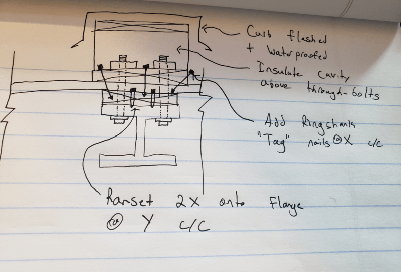
Anyways, since this is likely going to the graveyard, I thought I’d salvage this exercise and pose one last question about the connection (that will never be) between the roof deck and my portal frame. Since the shear connection would be pretty important to the portal doing its job, I figured simple nailing would not be reliable enough (e.g. wood rot due to lack of roof maintenance, bearing issues at fasteners due to cyclical racking , etc). So I was thinking of “sandwiching” the sheathing from above and below.

I’d build out a curb to make weather-tight my new connections. Plus add some sort of conventional nailing pattern just because.

A) Does this look like a decent conceptual detail?

B) How do others accomplish this? Is it just a 2x on the flange + nails from above and calling it a day? Any concerns of wood degradation around fasteners over time (or do people say meh to this as that’s a condition nearly everywhere)?
Assembly_z8g0w2.png
 
Enable said:
I figured simple nailing would not be reliable enough

But...that's how 99.9999% of wood diaphragms hold to their vertical LFRS. And I don't think your detail solves it anyway. You've added a lot of fasteners...but they all depend on sound diaphragm sheathing. Water can still leak here, and one might argue that it's more prone to a leak with all the fancy curbs and flashing. At least, most of the structural damage I've seen from flat roof leaks happen at seams - particularly those at the base of a curb or at the curb flashing.

Before you throw this out completely, take it over to the general Structural forum. Hopefully masonrygeek will pick up on it. He's sort of the go to on this board for all things masonry and, if anyone has a silver bullet up his sleeve it'll be him (or her...no idea, really).
 
AGREEING WITH pham

1) Masonry geek would be perfect for this. Most generalist EOR's rarely get too deep into the weeds with URM.

2) I agree that nails at the diaphragm boundary elements are fine. Wood normally does better with smaller, more frequent fastening than it does with larger fasteners.

BAD NEWS BEAR

3) Given that your partial, second story diaphragm probably represents a three sided diaphragm stabilized by a relatively soft rear shear wall setup, I'm not sure that diaphragm should be counted as wall bracing even where it does exist. Under seismic, the floor deck may actually count as out of plane lateral load on your walls rather than bracing.

HAIL MARY ATTEMPTS TO SALVAGE UR PROJECT

4) Maybe check Ontario's Part 9 section on residential construction to ensure that we're not missing some easy out here that one of your competitors might pick up on. I don't know of such an out off hand but stranger things have certainly happened.

5) Being Canadian, I also have the Drysdale book. He's actually very aggressive with some of his masonry design recommendations. For seismic, I believe that he actually has a procedure that allows the wall to crack in tension and continue to carry load as two diagonal struts, above and below the crack. Whether or not one can make a similar argument for wind load, I'm not sure.

6) The sketch below shows what I consider to be a slick, minimally invasive fix for this. Even if the client doesn't bite, I feel that proposing it would demonstrate some creative thinking and a willingness to innovate which is worth something.

C01_zhq9kl.jpg
 
Thanks for responding gents. I have some project updates but first want to respond to a few things

phamENG / KootK said:
Nails enough for lateral. Typical of wood.

Agreed that it is typical and probably enough. But I don't really enjoy thinking about how it, on a poorly maintained roof, will work over time. To me the bolts are better because instead of relying on bearing around the hole they induce friction that itself is enough to accommodate inplane shear.

But I will admit they are perhaps needlessly out of the ordinary for this kind of construction. I could probably be comfortable with the ramset 2x member + nails combined with screws going from the underside of the flange through the 2x member into the deck c/w fender washer.

KootK said:

That's a much different interior structure then I was envisioning so thanks for the idea! I also am concerned about the second floor for similar reasons, which is why I didn't consider it in my first go. I already put the idea of an interior portal further back into the home to cut down the span and that was immediately rejected due to the intrusive nature. I'll put this one to them in hopes they might like the look!

Project Update

Owner is okay with risks of core-filling and the GC is being forced by the owner to perform the work (he has a few other jobs with the same owner on a much bigger / commercial scale). So looks like we are not done....yet ha! However, I still have some masonry issues even with core-filling so I will be posting a separate thread in the structural forum. Should be fun!


Enable said:
To me the bolts are better because instead of relying on bearing around the hole they induce friction that itself is enough to accommodate inplane shear.

I disagree strongly with that. A friction mechanism requires pretension throughout the various faying surfaces in the joint, including the wood interfaces. Problems with that include:

1) I know of no reliable procedure for generating that pretention predictably as we have for slip critical stuff in steel to steel connections.

2) Any induced pretension is going to fade away over time as the wood creeps.

I have a question for the gang: does one expect URM to have starter dowels?

If yes, how doe one lap the new reinforcing with the starter dowels for shear connection? Or is shear connection not an issue?

If no, do we just rely on an unreinforced base connection for shear transfer? Just plain old friction?

 
I was writing a more detailed reply on how I agree with 2) but not 1) given friction's agnostic attitude toward surface area. But it became moot because I found a paper that indicates the relaxation over a 5-year period is so significant that it doesn't matter if you can get a handle on the initial pre-stress as after 5-years modeling seems to indicate only 3% of the original pre-stress will be contained in the bolt. I did not think it would have been that significant.

Relaxation of pretension of bolted timber joints under steady condition said:
after measurement, the joints were subjected to cyclic and monotonic loading tests until failure. The average ratio of residual stress to the initial prestress after 1 year was about 0.23 and 0.66, respectively, for joints without restressing and those with restressing. A simulated stress-relaxation curve developed from the four-element relaxation model predicted 3% of the initial stress after 5 years. Without a regular restressing program, the initial prestressing effect therefore must be considered negligible.


URM Question

....this is part of what I am about to ask in the structural forum. I have an issue at the interface between where the old grout / bar stops and my new grout / bar begins. Depending on how I treat that joint / what I have to do to integrate the old with the new the wall might work or not work.
 
Status
Not open for further replies.

Part and Inventory Search

Sponsor