Continue to Site

Eng-Tips is the largest engineering community on the Internet

Intelligent Work Forums for Engineering Professionals

  • Congratulations waross on being selected by the Eng-Tips community for having the most helpful posts in the forums last week. Way to Go!

Modifying Existing Transfer Beam | Sanity Check

Status
Not open for further replies.

bookowski

Structural
Aug 29, 2010
968
- This is a penthouse floor steel beam in a 1920's 20ish story building, construction is steel beams with concrete floors
- The original design did something clever & annoying. Because the penthouse had a unique layout the columns don't continue, instead they used single angle columns and stuck them all over the place in partition corners. I have original drawings but can barely read them so I can't figure out all of the framing or column locations.
- I need to modify a beam that carries one of these transfer posts. Since I can't figure out the framing I can't figure out the load on the beam
- I need to cut about 1/2 of the bottom of the beam for 3'-10" wide (new stair passing under). Since I don't know the load on the beam my approach is to reinforce to provide a new beam with >> Sx and >> Ix

Part of my concern here is that this beam passes into another residence that we have nothing to do with. It also supports a transfer post which in turn supports framing that goes outside of our client's unit. So any movement/issues may telegraph into neighbors, all of which are very expensive and likely contain cranky old ladies.

See attached sketch. The plan would be to build a kinked beam in place prior to cutting. One concern that I have is that the beam obviously needs to deflect to engage this reinforcing, how much might be tricky to figure out without knowing the loading. I could assume some service stress now - say 50% of Fy is conservative and do some analysis to figure out deflection.... I don't want to jack it much for fear of the same problems in reverse. Do I estimate deflection and jack say 1/2 of that? Don't jack at all but provide >>> Ix than I have now so that it takes very little strain to engage? Or is this just silly?
 
 http://files.engineering.com/getfile.aspx?folder=ed565640-0e83-4fb1-ba23-6a45c922569e&file=IMG_7041_-_Copy.JPG
Replies continue below

Recommended for you

Sounds like a good opportunity to push back on that stair geometry. 4" clip is not much to work around architecturally, but has major structural implications, not to mention cost.

If you need to cut it, I'd sum trib areas above for load, and also add a bottom "flange" plate at the top of the cut. Go high on all of it, and give that WT a healthy lap. Shore the beam either side of the cut, and jack it up to bear the existing dead load (until it just starts to move upward). Agree you should match section and then some.
 
I can't figure out the loads, hence my approach of adding back what's removed + extra.

Jacking until it just starts to move doesn't mean that you've removed the dead load. Theoretically it should start moving as soon as you put any load into it, i.e. if there's 10k dead load it would start going up at 1 pound and keep going until flat at 10k. There's also the issue that I'd be jacking against the floor below, so that's moving away at same time (and that is someone else's very expensive ceiling). This is why I'm hesitant to jack in this case.

I agree on pushing back on arch since this seems ridiculous but he's gotten himself into a pickle. Even with this clip he's giving code min head height right here and he was well down the path before I got involved so he's having a fit that it has to work.
 
Why don't you back-calculate what the maximum load is that the existing column can take, then design the transfer beam for that load.


Mike McCann, PE, SE (WA)


I follow about the jacking. I guess I'd jack to flat. Tough pickle.

What happens to the concrete slab where you are adding reinforcing? Can you engage any composite action (belt-and-suspenders)?

You asked about sanity check---if you clip the beam I think the sane thing to do is use a load you are sure covers you. Double (metal roof) or triple (concrete roof) the floor trib, I'd start there since you can't figure the L column layout and loads. That's what I meant by summing areas above---just superimpose the roof load using the PH framing layout.

Maybe arch could talk to the cranky old ladies,. Doubt they need the head height ;)
 
Conceptually, you could prestress the existing beam with a couple of heavy all-thread rods installed a few inches below the bottom flange of the existing beam and anchored each side of the opening using temporary stubs welded to the beam. The bars could be stressed against the stubs with turn of nut tightening prior to cutting the existing beam and prior to welding the new reinforcing on one side of the cut.

As the cut is being made, the tension in the bars could be monitored to maintain a desired amount of jacking or zero deflection. Welding of the top reinforcement could be completed after the cut is made. Bar tension could be slowly released and the bars and stubs removed.

Edit: I am not recommending the above method, just throwing it out as a possible consideration. Personally, I think I would advise the architect to come up with a different solution to his stair problem.

BA
 
Bookowski, your approach seems logical to me. If S & I are both greater than original, and if the welds are developed fully...well, I'm not sure why it wouldn't be. Are you planning for the connection between the bottom of the web of the new member and the top of the flange of the existing one to be a full-length, full-penetration weld? Or can you get by with less than that?

I'm looking forward to hearing more input on the matter from others...
 
Something to consider:
Is there a rational analysis method you can use to show the tension in the bottom flange flows around the notch, up through the stiffeners, etc. This type of solution would come in handy for many retrofit situations and I would be interested to know how the stresses can be analyzed, hopefully without FEA.

 
A kinked beam is ok, a beam with Sx and Ix > orig S and I is ok. I don't need to know the load on the beam to make sure it's ok for strength. What I'm worried about is how much deflection will I get for the new reinforcing to kick in. Since the beam goes outside of my client's condo and also supports a transfer post which in turn relates to areas outside our unit I need to worry about any deflection beyond almost zero.

I'm not sure how to make a reasonable stab at how much deflection I get from doing the reinforcing and shifting load into it. Since it's a small portion of overall length I'm thinking it won't be much. If I assume zero jacking (just shoring in place) I could do some attempt at modeling the beam with the kink and input a top/bottom flange strain into just the kink reinforcing to see how that affects the overall beam....? That seems like it will underestimate the actual deflection though. I could also model the existing as rigid and the kink as actual properties and see how much deflection comes from the kink...

Maybe i'm overthinking it. Original drawing attached for reference - i circled the post in red, beam cut is at the blue rectangle. These little angle posts are everywhere, impossible to locate them all to figure out the loading.
 
 http://files.engineering.com/getfile.aspx?folder=8af2907d-5225-4af4-a502-a26d0c98d42e&file=CPW_Orig_Dwg_-_Copy.png
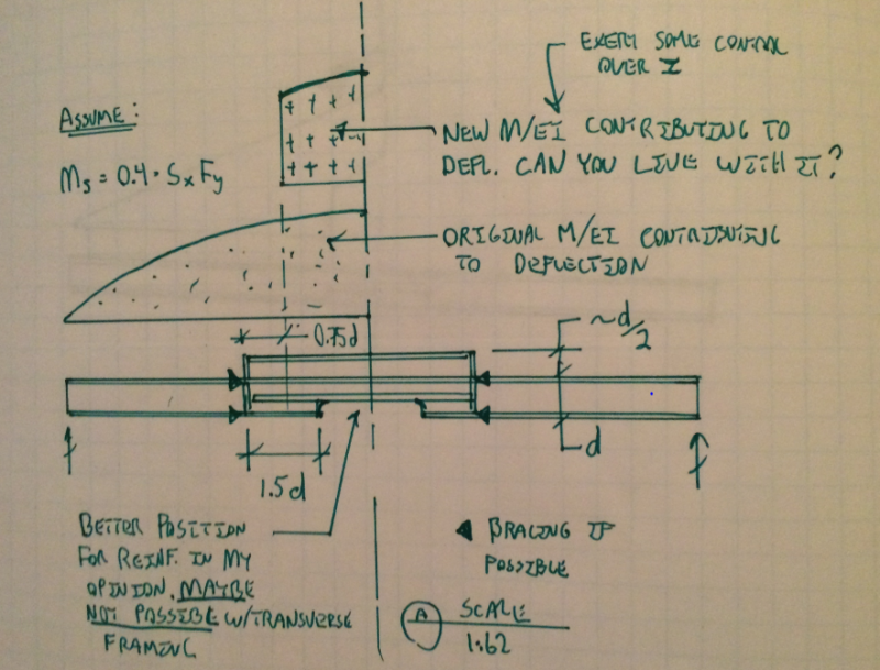
I like the method that you've proposed bookowski. Below is a sketch showing my musings on how I might approach the deflection calculation. I like my stiffener positioning but, based on intersecting beams etc, I understand that it may not be possible. I use jacking sparingly in situations where the jacked member is attached to a bunch of other stuff (slab etc) that may be helping to resist load in situ. I consider the potential disruption of those ancillary load paths to be a) scary and b) generally detrimental to stiffness.

Curious: spatially, how is it that you are able to accomodate the proposed WT reinforcement? Is it buried in the back wall of the stair opening? Does that limit how far you can extend it on either side?

Capture_01_wi7bpv.png


I like to debate structural engineering theory -- a lot. If I challenge you on something, know that I'm doing so because I respect your opinion enough to either change it or adopt it.
 
I'd like to do the horiz stiffeners as well but if you look at my first sketch the beam that actually carries the transfer column frames in just to the right of my cut. Money is sort of no object here so I could do some combo of both... or maybe modify the connection on that beam to get it out of the way although that's a bit scary.

Yeah I can basically run the wt as far as I want. It's a weird old construction oddity that is helping me out here. This is a penthouse and has terrace all around (overlooking central park!), instead of dropping the terrace slab like we'd do now they kept the framing flat and built up the interior with almost 1.5ft of cinder fill and then a topping slab on that. So I have that entire depth of fill slab to work in.

Your 'exert control over I' note is what I was thinking. If I give myself >>> more than I need then it should take very little strain to develop the force and thus very little additional deflection (hopefully). I'll have them survey it before and after to see what happens.
 
With 1.5 feet of cinder fill, would it be possible to run a new full length beam above the existing beam?

BA
 
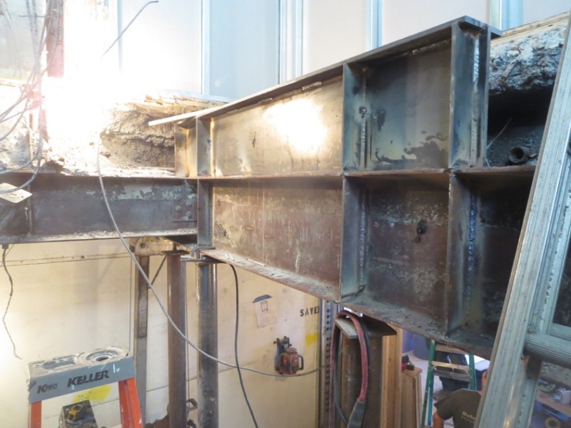
In case anyone runs across the same setup - photo of the reinforcing in place, cutting of the existing beam will happen soon. Due to the geometry I could only provide vert reinf on the photo side of the beam, on the far side is a horizontal stiffener (you can see some of the staggered welds reflecting through the web)

IMG_6389_-_Copy_mssqbp.jpg
 
Status
Not open for further replies.

Part and Inventory Search

Sponsor