Eng-Tips is the largest engineering community on the Internet

Intelligent Work Forums for Engineering Professionals

Moment Connection to a Knee Brace

Status
Not open for further replies.

BS2

Structural
Feb 10, 2012
65
0
0
US
I have a unique framing situation for a mechanical structure designed under Chapter 13 of the ASCE 7-16. The seismic loads are large (SDS = 1.2).

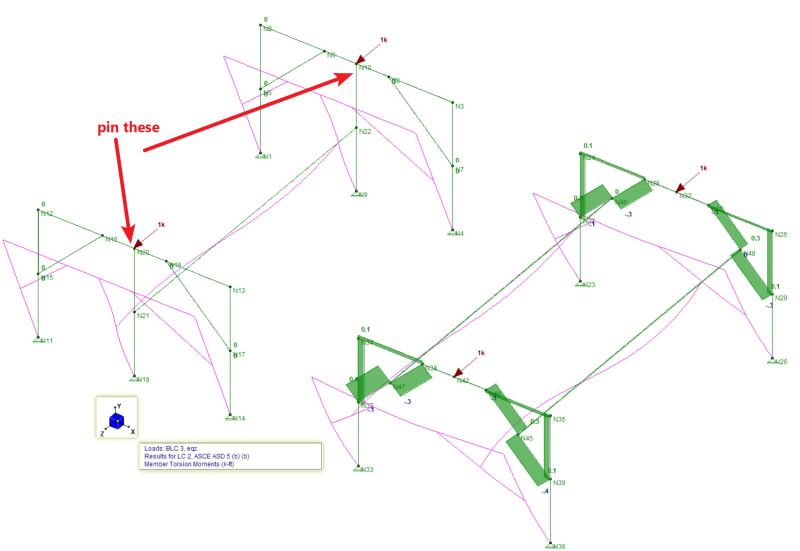
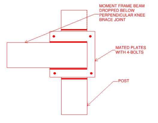
The attached RISA output shows one bay of a knee braced frame. This structure supports some equipment. Due to other space constraints not shown, the only reasonable area to include lateral bracing in the longitudinal direction is with a beam moment connected to a knee brace. This would load the knee brace in torsion. The planned connection would be an endplate connection with two bolts.

For reference, the columns are approximately 4' tall and are HSS3x3x_ or HSS4x4x_. The beams are HSS5x3x_.

QUESTION: Is this type of configuration allowed in SDC D under Chapter 13 of the ASCE 7-16? I know it isn't ideal or preferred but there are not many options.

Thanks in advance!
 
 https://files.engineering.com/getfile.aspx?folder=a067ddf9-ec70-40e8-8cac-d6b59ab8e655&file=Kick_Brace_Moment_Frame.jpg
Replies continue below

Recommended for you

I'm not sure I fully understand your question. Some questions for you?
1) What is the purpose of the lateral bracing in the long direction?
a) Does it support gravity load?
b) If not, why not just design the two frames independently as cantilevers in that direction?

2) Which connection are you asking about?
c) The long brace to the kicker?
d) The kicker to beam and kicker to column connections?
 
BS2:
Don’t just use a knee brace. Make the HSS 5x3 beam, however long it is, and then at N106 have it turn up to N94, through a welded moment corner connection. Do the same thing at the other end, N105 to N92. Now, make the knee brace in two shorter pieces, with end pls. either side of N106, through bolted at this new beam corner joint (N106). The beam is shop fabed. with the two short legs and nasty end connections up at N94 and N92. You might also put a knee brace, or some such, from N94 out onto the beam, in the inclined plane along the beam. That entire joint, column portion, long beam portion and short beam portion will fit in a 3’ or 4’ cube. Why not shop fab. that entire joint and then bolt on the remaining column, long beam and short beam portions in the field, near their inflection points. You have to work out the details.
 
Thanks for the responses!

JoshPlum:
My question is primarily about whether I can design a moment frame in a high seismic zone with this or a similar configuration. Not shown on this model (but shown on the picture below) are a couple of other longitudinal beams which bear slightly inboard from the knee braces. My original plan was to use these moment connected to the cross beams. This would introduce quite a bit of torsion into the beam. I have never seen a configuration like this used.

1) The purpose of the lateral bracing in the long direction is to resist seismic forces.
a) The beams shown connected to the kick braces do not support gravity loads. The gravity loads are supported by two additional longitudinal beams (shown below in red) directly on top of the short beams with the kick braces.​
b) This structure supports equipment that wraps around the top and sides of this frame so this is just about the only place for bracing.​

2) I am primarily asking about the long beam to kicker connection and configuration. I am confident that I can make the lateral loads in the short direction work with kick braces or even end plate moment connections.

dhengr:
Thank you for the feedback. I think that would be a possibility to turn the beam 90 degrees and have a complicated corner joint. There is other equipment completely surrounding and wrapping around these beams so we can't run extra braces. I have attached a screenshot below of a rough draft of the connection.

Destination_Kick_Brace_Connection_fwutze.png


retired13:
On past projects, we have cantilevered the columns from the concrete slab. This project bears on a mezzanine and there isn't a practical way to increase the anchoring capacity to meet the loads at this site.
 
I'm confused on what you are trying to achieve with that member. It doesn't seem a particular good way designing a moment frame. What wrong with attaching the member to the column?

You current 'solution' has horrendoes torsion on the knee brace not to mention terrible prying forces on the bolts.
 
It isn't right. During a seismic event, the two horizontal members will simply go along with the end frames when move in the long direction. At that stage, each column will experience torsion in two directions and a horizontal thrust at the column-knee brace joint. Albeit complicate, you may be able to design the members and connections to satisfy strength requirements, but stability remains the top issue to be resolved.
 
OP I wouldnt try to do what you're trying to do. That said:

I have no idea what sort of equipment this is, or any dimensions (aside from 4' tall), or loads, or anything like that. But assuming you can't put anything on the exterior posts...can you put a post in the middle? Then you could put a bending member ("moment frame beam") between the two center posts. Pin the top of the two center posts by using some sort of double angle with through bolts or something to eliminate torsion on the "N94-N88" type beams. Obviously this is another ill-advised solution, but I'm bored and have nothing better to do. Here's a 5 minute model of your's versus mine. Forgive my sloppy modeling.

sillyframe1_t9dp7g.jpg


Edit to add: ive fixed all members except the two with arrows pointing to them, under the assumption that the loads are light enough for these connections to provide some degree of fixity...FWIW. Pinning everything, but torsion still fixed:

Also this is at 250x magnified deflection.

sillyframe3_hbe8ka.jpg
 
Yours is a clever solution and it's not as though you don't have a genuine load path. My concerns would be:

1) Difficult to find robust methods for designing the connections.

2) Tough to assess joint stiffness with confidence. I'd be concerned about that if this thing's holding up a heavy unit that might tend to flop over P-delta style if frame stiffness is lacking.

See the sketch below for another alternative to add to the heap-o-solutions if there's space. Inside of the verticals and just below the lower knee joint connection of the perpendicular frame. Bolts in shear should make for a pretty stiff connection that would be easy to evaluate.

c01_sspkwq.png
 
Status
Not open for further replies.
Back
Top