Continue to Site

Eng-Tips is the largest engineering community on the Internet

Intelligent Work Forums for Engineering Professionals

  • Congratulations IDS on being selected by the Eng-Tips community for having the most helpful posts in the forums last week. Way to Go!

moment magnification BS 8110 vs ACI 318 1

Status
Not open for further replies.

Enhineyero

Structural
Sep 1, 2011
284
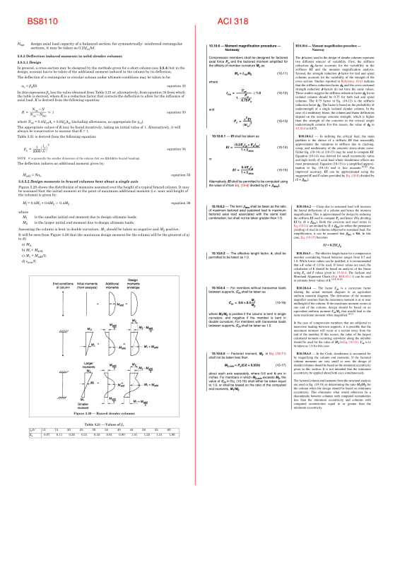
Is there anyone here who can explain why the column moment magnification formula of BS 8110 vs ACI 318 is so different? And somehow BS 8110 makes more sense particularly if you design the column as pin-pin (lateral stability by shear walls). Any help would be appreciated.

Document1_kbmjbo.jpg


Here is a link, realised the pic cant be read.

 
Replies continue below

Recommended for you

I'd never seen that BS8110 method before, so only know what I've read over the past day or so. Thanks for posting; it's quite a tidy method. Is BS8110 still a current code somewhere that you're designing to, or is this just for interest? The Eurocode has the same basic method (as well as a method similar to ACI) but with a different calculation for the balanced curvature. I gather BS takes the curvature as h/(200*b'^2) but couldn't find a derivation of that. The Eurocode version was easier to follow.

I assume that ACI vs BS was just a matter of preference/knowledge of the respective code authors at the time.
 

I have BS 8110 1997 and i think superseded and withdrawn... But i remember the procedure..
BS 8110 assumes the curvature ( 1/ρ) = ( εc+ εs )/d and for balanced condition εc = 0.0035 and εs= 0. 002 so the curvature for balanced cond. ( 1/ρ) = ( 0.0035 + 0.002 )/d = 1/(182d)

One can get the deflection by integration of curvature. If you assume rectangular curvature distribution δ =L**2/ 8ρ and for triangular δ =L**2/ 12ρ and apparently the code preferred δ =L**2/ 11ρ for the design .

Additional moment is calculated with Madd = N*α u and αu = βaKh

The correction factor K accounts for that the failure is compression failure rather than balanced failure and the interpolation proposed by the code is the compression portion of the interaction curve.

K= (Nuz – N)/(Nuz – Nbal ) .. This formula requires iteration since we do not know the steel ratio so the Nuz ..

 
Steveh49 - I'm no longer using BS 8110 but have used it for a long time, I like its simplicity and the way it explains some of the formula (without the need to read a different document). The way BS 8110 presented the slender column moment as an additive (instead of increasing the moment from the analysis by multiplying it using a certain factor) makes it easier to understand and apply. Not sure if both formulae would end up with similar design moments.

Also, not sure how to design a column using ACI when plastic analysis is used, beam end moments are usually zero (do you then use the min. eccentricity moment and magnify that?)
 
Enhineyero - I was thinking the same, that the BS description of the method included just enough 'textbook' info to understand generally how it works. I think that's out of favour with code writers these days. I'd refer to Eurocode rather than BS8110 if using the method these days, because it is current.

Does ACI give plastic design requirements? Why are the end moments zero? Wouldn't they be the plastic capacity of the beam, or have I misunderstood?


Hturkak - I figured the 1/2000 factor in BS8110 was 1/(~200 * pi^2) as I didn't know what exactly concrete strain and steel stress were used for design and needs to be adjusted for cross-section dimension vs effective depth, but would be ~1/200. Pi^2 is for sinusoidal deflected shape, compared with your 8 for uniform curvature and 12 for triangular curvature. But how does the 'h' in the numerator fit in, and the (b')^2 in the denominator? For weak-axis bending, h/(b'^2) = 1/b' because h=b', and that's what we're after. But strong axis doesn't give the same result.
 

For the balanced failure mode , εc = 0.0035 and εs= 0. 002 are the strain for the concrete and steel..

The additional moment for the deflection δ is M add= P* δ and with your post i started to think that δ =L**2/ 10ρ , the figure 10 could be the average of rectangular,triangular, and sinusoidal curvature distribution.

if we put the δ value at Mad=P*L**2/ 10ρ and for ρ=1/(182d) , Mad= ( P*d (L/d)**2)/1820 . And the figure 1820 is rounded to 2000 .
The code has a NOTE = ( b' is generally the smaller dimension of the column (but see 3.8.3.6 for biaxial bending).

IMO, for rectangular columns , the additional moments should be calculated for b and d separately.

Madx =( P*d (L/d)**2)/2000 and Mady=( P*b' (L/b')**2)/2000 ..

 
Does ACI give plastic design requirements? Why are the end moments zero? Wouldn't they be the plastic capacity of the beam, or have I misunderstood?

Steve - I usually assume a pinned connection between column and beam (lateral load resisted by shear walls), effectively minimising any moment transfer to the column. I still check the column cracks at service level.

One can get the deflection by integration of curvature. If you assume rectangular curvature distribution δ =L**2/ 8ρ and for triangular δ =L**2/ 12ρ and apparently the code preferred δ =L**2/ 11ρ for the design .

HTURKAK - Can I get a resource for the derivation of this formula?
 
Status
Not open for further replies.

Part and Inventory Search

Sponsor