Eng-Tips is the largest engineering community on the Internet

Intelligent Work Forums for Engineering Professionals

Monorails - combination of stresses 3

Status
Not open for further replies.

CDLD

Structural
May 20, 2020
209
1
18
CA
Good afternoon!

I'd like to get opinions from others regarding the combination of normal stresses in a singly-symmetric monorail beam according to A360-16 and AISC design guide 9.
Typically, we design for a lateral load applied at the bottom flange and a vertical load with an impact factor.

We usually do a buckling / capacity check in accordance with design guide 9 as well as a stress check.

For the stress check, we check top and bottom flange separately.
We combine the stresses and ensure the top and bottom flange remain less than phi*FY (elastic).

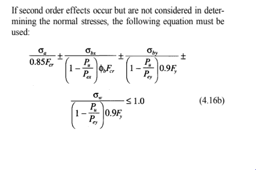
For the capacity check, I have attached a sketch which shows how I intend to combine the stresses for both top and bottom flanges (checked separately again).

Now for the question...

For the capacity of the bottom flange (under global tension), is it reasonable to use the full tension flange capacity (assuming LTB would only apply to the top flange check)for the vertical load component?

I believe the attached sketch will help convey my question if it is unclear.

Thank you!
 
 https://files.engineering.com/getfile.aspx?folder=1e7dc383-5a52-4912-81a8-51624c39b1cc&file=monorail_forces.pdf
Replies continue below

Recommended for you

I use LTB for the bottom flange usually, but generally don't use capped beams for monorails as it is somewhat inefficient, so the check is no different to the top flange check. Often the local stress in combination with global stresses evaluated against F.y (not F.cr) govern anyway. ASME BTH-1 (and EC 199?-6?) have formulas to calculate local stresses.
 
Thanks for the comment, It's definitely more conservative to use the LTB strength at the bottom flange check, whether it's correct I'm not sure.
I guess in a way it makes sense to use the LTB strength because it's a global effect, but still I'd like to know for sure because it has a large design impact.

You may find this useful:
For the local stress combinations between longitudinal and transverse I tend to check Von Mises equation using serviceability loads to prevent large-scale yielding.
Using serviceability loads usually prevents this from governing the design.

For ultimate strength you can ignore the interaction between longitudinal stress and local wheel stresses so long as the bottom flange is in tension. You can make use of Bo Dowswell's paper " Flange Bending in Single Curvature". See images below.
Screenshot_2023-03-17_145048_arnet2.png
Screenshot_2023-03-17_145031_wmwqo7.png
 
I don't think that means you can ignore the wheel stresses in combination with beam flexure, just that you don't need to reduce the capacity of the yield mechanism when the beam is in combined flexural and local loading. In any case, the member carries neither axial tension not compression, it is loaded in flexure.
 
1.
It depends on how you distribute the stresses from the wheel load.
Typically, I use an equivalent width approach and treat the bottom flange as if it's cantilevered from the web.
This would mean that all local wheel stresses are transverse to the beam axis.

If you use some of the fancy CMAA equations (which I assume you have in mind) than the wheel loads will cause both transverse and longitudinal stresses, in which case, yes, you'd have to consider these local longitudinal stresses in combination with beam flexure.

2.
Yes, the beam is loaded in flexure, however the bottom flange, which is where the interaction occurs, has tensile normal stress. I believe, the author is saying that the longitudinal tensile stress would have no impact on the yield line pattern from local wheel stresses in the transverse direction (for plastic design).
For strength design, you can check the local flange bending independently from the longitudinal flexural stresses (using an equivalent width approach)- as long as the bottom flange carries tension.


Curious what you think about this.
 
1. Transverse stresses and longitudinal stresses still have an interaction per von mises criterion. If this doesn't yield at service loads, the yield line mechanism should have lots of reserve capacity in the ultimate state, but they are still combined.
2. Under plastic strength - "When the main member carries axial compression'... talking about the beam, not the flange imo. "When the element carries axial tensions".. could be interpreted as you have. Either way, still need a combined check I believe, just without reduction of the yield line capacity. In any case, not yielding under service loads should govern.
 
I do agree that Von Mises criterion should be verified at the service load level for elastic stress distribution.
I have attached the article in case you do not have access to it - it is very useful.
The "reduction factor" referenced in the article is actually another way of expressing the interaction equation (The author also expresses the Von Mises equation as a reduction factor). The reduction factor is applied to the local flange strength as a way of encapsulating the interaction between transverse and longitudinal stress.
So when the author states that the yield line strength is not reduced when the element carries axial tension, I believe he means that the interaction is not critical (for plastic design, again).

My guess to the author using the term "axial compression" rather than longitudinal stress is to remain consistent with the original research he is referencing.
I can't think of any reason why a flange that is under flexural tension or compression would act any differently (or be more critical) than a flange under axial comp/tension when interacting with transverse stress.

I am curious to hear from others opinion on my original question but I have appreciated this discussion on local wheel load interaction nonetheless.

I feel like this would be up KootK's alley.
 
 https://files.engineering.com/getfile.aspx?folder=c1b2756e-6997-4c77-9c39-8736c3616799&file=Local_Flange_Bending_-_Bo_Dowswell.pdf
The AS code on cranes and monorails has an empirically derived formula that is essentially a canned solution for monorails it includes interaction effects. I think the BS also have something similar.

I find it all a bit black box of a calculation but it is pretty straightforward and conservative. If require I'm happy to post it here.
 
Already have the paper... getting side tracked on wheel loads though. If you read through S16 on singly symmetric sections in bending, it says to check LTB for each flange that experience compression along its length.
 
CDLD said:
We combine the stresses and ensure the top and bottom flange remain less than phi*FY (elastic).

So, you're combining the torsional warping stresses with the weak axis bending stresses compared to the yield. But, when you add in the strong axis bending stress you're comparing that only to the LTB limit? Then those two checks are just added together and compared to 1.0. Yeah, that sounds reasonable to me.

For the bottom flange (assuming it's always in tension), comparing it to yield seems reasonable as well.

That being said, my philosophy (when looking at a cap channel) crane rail beam like shown in your calculation images, is something different.
a) The weak axis bending is entirely taken by the channel. With the idea that the centroid of the weak axis load will be at approximately the shear center of the channel, meaning no torsion results.... just weak axis channel bending.

b) The strong axis bending is taken entirely by the wide flange.

c) No interaction equations needed.

I like this philosophy better than yours. It's probably more conservative. Though in might mean you have to play with the cap channel size to manipulate where the shear center is for the channel to get it to line up with the centroid of the lateral load.
 
CDLD said:
@human909
If you don't mind I would be interested in that equation.

As requested. From memory the commentary mentioned that the formula was based off empirical testing in the 70s. When I first began designing monorails I compared it to other international sources and calculations. In general it seemed conservative. Since my initial few designs I've largely accepted the 'black box' nature of it and churned out designs.

For what it is worth I used load factors of:
Hook and Sundary 1.2
Dynamic Factor 1.25
Total Factor 1.5

monorail_t83xk3.png
monorail2_p76ite.png
 
CDLD said:
I feel like this would be up KootK's alley.

I do so love a summons. This might take a little back and forth, we'll see.

I agree with your unstated hypothesis here which I take to be this: since the top flange is doing the lion's share of the work in resisting LTB, including LTB in the bottom flange check seems unduly punishing.

I imagine that the equation shown below was initially developed with dually symmetrical sections in mind. Wide flange beams and such. In checking LTB for such sections, we rely upon the following for torsional restraint:

1) Ix of both flanges.
2) St. Venant torsional stiffness.
3) Warping torsion stiffness.

This makes it tough to strip LTB away from a bottom flange check because all three of those mechanisms involve the bottom flange and will tax it to some degree. A beam with a channel cap is a bit different, however, in the following ways:

4) The neutral axis will be closer to the top flange.
5) The channel will provide a great deal of lateral stiffness in its own right.

With those things in mind, I propose the following, alternate procedure.

6) Use an alternate LTB checking procedure where the channel and top flange are treated as a faux column resisting all of the flexural compression with no help from J, Cw, or the Ix of the bottom flange. Another way to view this is to think of it as the channel bracing the top flange.

7) Do the interaction check on the top flange using the LTB capacity s described above. This may be a bit more punishing than the conventional method.

8) Do the interaction check on the bottom flange without LTB.

This involves a couple of assumptions:

9) The full beam cross section is capable of bracing the faux column vertically and torsionally.

9) LTB about a point in space located at the intersection of the flange and web is unlikely to govern.

C01_aqjfea.png
 
Thank you all for your responses.

Kootk, I appreciate your input and validation that the bottom flange contributes to LTB stability to some degree.

Your alternate procedure seems very reasonable.

This could be useful for a check on an existing crane beam, although for new designs I'll likely take the conservative route and include LTB in the bottom flange capacity check.
 
...and the impact of the load location and the shear centre for the bottom flange loading.

-----*****-----
So strange to see the singularity approaching while the entire planet is rapidly turning into a hellscape. -John Coates

-Dik
 
Status
Not open for further replies.
Back
Top