Continue to Site

Eng-Tips is the largest engineering community on the Internet

Intelligent Work Forums for Engineering Professionals

  • Congratulations MintJulep on being selected by the Eng-Tips community for having the most helpful posts in the forums last week. Way to Go!

Motor contributions to earth faults 2

Status
Not open for further replies.

bspace123

Electrical
Sep 3, 2009
27
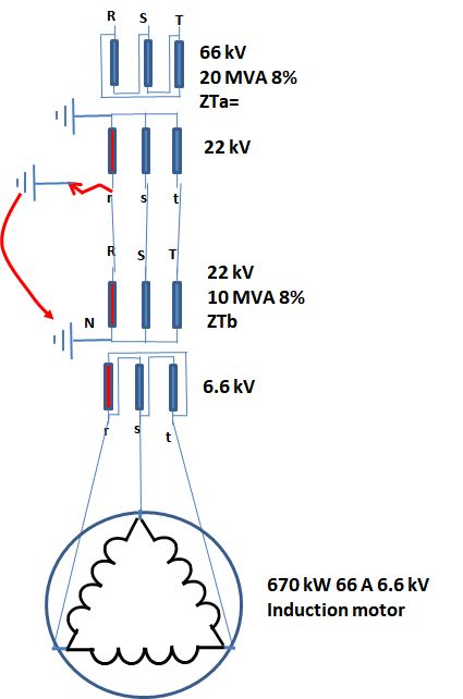
Consider a delta/Wye 66kv/22kv transformer supplying a bus then from the bus a feeder supplying another delta/eye 22kv/6.6kv transformer. From this second transformer a bunch of DOL motors are powered.
The delta sides of the transformers are not earthed. The Wye sides are at their star points.

If an earth fault occurs between the two transformers, say on the bus, will motors contribute to the earth fault? My understanding is that motors will only contribute to phase-phase faults as the delta/Wye transformer supplying the motors is not earthed on the delta side?
 
Replies continue below

Recommended for you

My answer is,yes.
The contribution is due to trapped flux inside the motor during a fault on the bus.
Therefore, even for a single phase to earth fault, the 6kV motor contributes to an earth fault between the two transformers.
The actual currents contributing to the fault will be smaller than its contribution to a 3-phase fault on 6.6kV side,
due to the ratio of transformation 3.333 towards the 22kV side.
 
But where is the fault path? The second transformer is now acting as a step up transformer to what is generated current from the motors. There is no ground fault current path back to the delta side?
 
On the 22kV side of the 22/6.6kV transformer, the motors will not supply supply zero sequence current into the fault because the delta winding can't source zero sequence current. They can, however, supply positive and negative sequence. That positive and negative sequence can then flow to the wye winding of the 66/22kV transformer and become zero sequence current that flows back to the fault from the transformer.

The fault draws more current if the motors are there (to the extent that the motors actually source fault current), but they only indirectly supply the additional fault current. The motor contribution is short lived and may be insignificant compared to other sources.
 
It looks like you are talking only about zero seq. currents at the fault location. Despite the fact that the motor is UNEARTHED,
the motor will contribute currents to an earth fault on the 22kV DELTA side. This is because the motor will produce positive
and negative seq currents to the fault.But no zero. seq. current contribution.

If you draw the three seq. networks at the fault location you will see what I am talking about. For a single phase fault to earth,
the three networks to be added in series.
 
If all 3 phases are short-circuited then no supply voltage and the EMF in stator windings are from the rotating remaining magnetic field in rotor up to demagnetizing.
If one phase is missing the rotor still rotating in the same direction but the magnetic field is split in two: one direct rotating in the same direction with the rotor and the second is rotating in opposite direction. So we have two EMF's in all three phase windings -one direct sequence and one opposite sequence.
The phase s and t connected with remaining healthy phase the direct EMF is compensated by supply voltage but the opposite does not. At transformer Tb secondary phase rs- 6.6 kV- it is magnetically connected with RN [22 kV] and so, in my opinion, the current supplied by the phase rs of the induction motor contains both components.
I take an example of 66/22 kV 20 MVA 8% ,22/6.6 10 MVA 8% and a motor 6.6 kV 670 kW [66 A rated 6.4*66=422.4 LRC ].
Vbase=22 kV
The maximum EMF produced it could be: 6.6 kV.
The motor direct impedance it is: Zm6.6kV=6.6/sqrt(3)/0.4224=9.02 ohm
At 22 kV the motor impedance will be: Zm=Zm22kV=Zm6.6kV*22^2/6.6^2=100.2 ohm
The opposite motor impedance will be the same.
Neglecting the resistances and the transformer Tb Zo the motor contribution will be:
Iscm22kV=22/sqrt(3)/(2*Zm+2*ZTb)
Iscm22kV=22/sqrt(3)/(100.2+3.872)/2=0.061025 kA
If we compare this current with the short-circuit current supply from the System[Grid] then:
if we take 3000MVA SYSTEM Short-circuit power then Zsys22kV=22^2/3000=0.161 ohm
ZTa=22^2/20*8%=1.936 ohm
ZTb=22^2/10*8%=3.872 ohm
The the short-circuit current at 22 kV supplied from System it is:
IscSys=22/sqrt(3)/(0.161+1.936+3.872)=2.128 kA
Iscm/Isc=0.061/2.128*100=2.87%
6.6_kV_INDUCTION_MOTOR_CONTRIBUTION_TO_SHORT_CIRCUIT_yqc1zj.jpg

 
Sorry!.Zb is not involved in IscSys. Then IscSys=22/sqrt(3)/(0.161+1.936)=6.057 kA and
Iscm/Isc=0.061/6.057*100=1%
 
But when starting the motor current is about 6 time running current. Slip is system frequency and impedance is 1/6 running impedance.
With a bolted phase to phase short, the system frequency drops to zero. With the motor spinning at rated speed the slip frequency is about 98% of the system frequency.
With a bolted three phase fault I understand that the motor contribution will be closer to locked rotor current than to running current.
The motor will be acting as an induction generator. I understand that in the event of a two phase fault on a delta generator, the shorted winding delivers 1/3 of the total energy and the other two phases act as an open delta in parallel with the faulted phase and also deliver 1/3 of the total energy. The result is 2/3 of the energy delivered to a three phase fault.

Further explanation.
Consider a bank of three transformers in delta.
Each transformer will deliver 100 Amps at 250 Volts or 25 KVA.
Line current will be 100 Amps x 1.73 = 173 Amps.
Capacity of the bank will be 3 x 173 Amps x 250 Volts / 1.73 x 1000 = 75 KVA
A single phase load on the bank will be fed 50% by the in phase winding and 50% by the other two windings acting as an open delta in parallel with the in phase winding.
The result is that the short circuit current into a phase to phase short is 2 times the available short circuit current of one winding or transformer, not the 1.73 times it would be with a three phase short.
To add a little safety factor round up to 7 times locked rotor current for the motor contribution.
I would use a figure of 6 times running current for a three phase bolted fault and 115% of 6 or 6.9 times running current for a phase to phase fault for a delta connected motor.
To check these figures, consider a delta transformer bank consisting of three 25 KVA transformers.
Open connections so that you have a single phase transformer and two transformers connected in open delta.
Connect the load to the open delta. Calculate the impedance of the open delta using a phantom load.
You will see that when the phase angles are considered, the virtual transformer formed by the open delta is similar to the single phase transformer that was removed from the bank.
When a single phase load is connected to a delta bank the bank acts as a virtual transformer in parallel with a real transformer with similar characteristics equal current flows through each transformer.
Don't believe me? In many parts of the world it is common to see a large distribution transformer, say 50 or 100 KVA paired with a 10 KVA transformer in open delta to provide a small amount of three phase power.
No problem, but add a second 10 KVA transformer to close the delta and wait for the smoke. It won't be long. The 10 KVA pigs won't take half of the load of a 100 KVA transformer.

Worst case: 66 Amp motor x 6.9 x 2 = for a single phase fault = 911 Amps at 6.6 kV = 273 Amps at 22 kV. (Reduced by conductor impedance and by transformer impedance.)
Bill
--------------------
"Why not the best?"
Jimmy Carter
 
Thank you, waross.Your approach by compare this phenomenon with an open-delta transformer it seems to me very interesting
 
Status
Not open for further replies.

Part and Inventory Search

Sponsor