Continue to Site

Eng-Tips is the largest engineering community on the Internet

Intelligent Work Forums for Engineering Professionals

  • Congratulations SDETERS on being selected by the Eng-Tips community for having the most helpful posts in the forums last week. Way to Go!

Motor Efficiency and Power Factor at Part Load.

Status
Not open for further replies.

Pavan Kumar

Chemical
Aug 27, 2019
393
Hi All,

I was able to perform pressure drop calculations for develop the system curve with two dissimilar pump using the guidance provided in the below thread. The pump and system curves are pasted below for your reference. I can post the excel calculation spreadsheet also if needed.
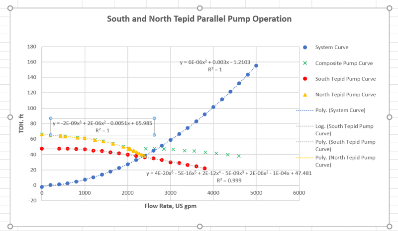

Parallel_Pump_Curves_iqwlaa.png


Since I was not able to get the required flow with pumping in parallel, I worked on the option to raise the RPM of the current motor from 1200 to 1800 RPM. The motor HP has increased from 30 HP to 100 HP. We are still checking the feasibility of this option. We are going to use VFD to adjust the RPM as required. I have the Load Performance Curve for the motor (see attached). I want to know the power factor and motor efficiency to calculate the power input required to calculate the electrical power cost / year. My question how do I determine at what percent of the rated output power I am operating my motor. The data I have is based on my pump pressure drop calculations is the Flow rate, head and pump efficiency at the duty point. As you can see in the Load Performance curve the while the motor efficiency more or less remains same as the load decreased the power factor gradually reduces. I want to use the power factor and motor efficiency at the load I am operating at.

Thanks and Regards,
Pavan Kumar
 
Replies continue below

Recommended for you

Pavan,

I am not quite clear on what change you are doing. It sounds like you are considering replacing the motor on one of the current pumps to go from 1,200 to 1,800 rpm, then controlling flow with a VFD such that only one pump will be needed. If this is the case, and if the pump is capable of such an upgrade (ask the OEM!), then this should be fairly simple.

First, you need to obtain the pump performance curve from the original equipment manufacturer (OEM) for pump speeds 1,200-1,800 rpm. They may not have various rpms, so you could try to interpolate via affinity laws if you only have a 1,200 and 1,800 curve. If they do not have performance curves for at least 1,800 rpm operation, I'm not sure that you will be able to do the next steps with any significant accuracy.

Then, using your pump curve and system curve, determine where your operating point is on the pump. This should give you hydraulic power, which you then multiply by the efficiency of the pump (again, interpolation of the efficiency zones may be required!). This should give you the load of the motor, which you can then compare to the rated motor load to determine what %load the motor is operating under.
 
So when at 1800 rpm on the red pump you're looking at about 3600 gpm max flow.

Good enough?

Why the VFD?

Don't forget to factor in the losses in the VFD, about 8 to 10% of the power going out adds to the power used.

Remember - More details = better answers
Also: If you get a response it's polite to respond to it.
 
Also what efficiency are these pumps running at?

I did a quick check on the red pump and at 70% eff it required >30hp shaft power.

SO your motor looks undersized to start with.

Before making such a big change to the pump you do need to find out from the OEM if this is possible and what the pump curve looks like.

But what sort of velocity in the pipe are you looking at? It seems to me you're getting close to the economic flow rate now at around 2,500 to 3,000GPM so trying to get more just costs you more and more for every additional GPM.

Remember - More details = better answers
Also: If you get a response it's polite to respond to it.
 
Hi TiCl4,LittleInch,

I apologize for the delay in my reply. Currently with one pump we are able to get around 2300 US gpm flow. We want to increase the flow to around 3500 US gpm to help increase heat transfer on a downstream heat exchanger to which the tepid water pumped by these pump(s) is on the shell side. My calculations with parallel pumping ( curve shown in my first post) showed that I can only get 2500 US gpm, a marginal increase over single pump operation. The pump suction and discharge line sizes are 10" Sch 40. The velocities in these lines are 14.6 ft/sec at 3600 gpm flow. Much above the 9 - 12 ft/sec limit. Also there is lot of wasted energy. We will replace the lines at the next turn around. We need the flow immediately to stop losing product due to in-efficient cooling in the heat exchanger. The heat exchanger will also need replacement but that is another project that we will work on soon.

Yes you are correct in your judgement that I am trying to install a motor with 1800 RPM to replace the current 1200 RPM , 30 HP one. I checked with the pump supplier and they said it is compatible with 1800 RPM motor. I had the pump curve at 1200 RPM and generated the one at 1800 RPM using affinity laws. I can ask the manufacturer to give me a curve at 1800 RPM but I feel it will be the same as what I generated using affinity laws. Let me know what you think.

Q2 / Q1 = (N2/ N1)
H2/ H1 = (N2/N1)^2

where Q1 and Q2 are flow rates in gpm
N1 and N2 are motor rpms 1200 and 1800 respectively. I used 1180 and 1775 actually.
H1 and H2 are the differential heads at Q1 and Q2 respectively.

My calculations showed that the motor hydraulic power required is 92 HP, so a 100 HP motor will be required. Attached please see the pump curve.

I calculated the hydraulic power as below

At the duty point:

Flow Rate = 3613 US gpm
Head required( DH) = 87.96 ft
pump efficiency( n) = 0.86 ( from the pump curve) <--- Please let me know if I am correct here.
Density = 61.36 lb/ft3
Mass flow rate(m) = (3613*0.133681/60)*61.36 = 493.95 lb/sec

Hydraulic power = m * DH / (n*550) = 493.95*87.96/(0.86*550) = 91.8 HP

At full load:

Power factor(PF) = 0.82
Motor efficiency(EFF) = 0.93
Voltage = 575 volts
Power supply = 3 phase.

Input power required(PMotor) = 91.8 /(0.82*0.93) = 120.45 HP

PMotor = 1.732*V*A*EFF*PF/ 746 HP

from this full load amps (A) = 120.45*746/(1.732*575*0.82*0.93) = 118.3 Amperes.

Also with power cost = $0.13/KWH and working days = 351 / year
I calculated the electrical power cost = $ 98,363 / Year.

I have not added the power loss due to VFD. I need to know how to add that too.

Now coming to my question on how to determine the PF and motor efficiency at part load. We are going to have a VFD to reduce the RPM as the process demands and to save power. Say if we run the motor at 1500 RPM, I want to know from Load performance curve for the motor how can I determine the PF and Motor efficiency for part load. Lets says we get 2800 US gpm at 60 ft head and the pump efficiency is 0.75. How do I know what is the load and rated motor power output to determine the % of rated power output?.

Thanks and Regards,
Pavan Kumar


 https://files.engineering.com/getfile.aspx?folder=e0aa7c46-67bf-4f46-b1fe-e711a9f19042&file=Pump_Curve_with_Efficiency_Curves.pdf
You don't look very far to find this
go to the bottom of page 17 for 1750 rpm and your pump is there - noting that your impellor diameter is 10.3" so somewhere between 10" and 10.7" curves.

At your desired flow of 3500 your efficiency is reading about 75% and just under the 100 hp shaft power line.

Then add motor efficiency to get your input amps.

Power factor is all about kVA and reactive power which I've never understood, but I don't think you calculate it that way.

VFDs suck about 8-10% of the power out on top.

I would fit a fixed speed 1800 rpm motor and a control valve.


Remember - More details = better answers
Also: If you get a response it's polite to respond to it.
 
Pavan,

1st, the affinity laws are good for extrapolating smaller changes in pumps. Using them to go to 1.5x of the existing motor speed will not be the same as what the manufacturer finds from performance testing. You'll need OEM data to get accurate results.

2nd, your power calculation doesn't appear quite right.

Q = 3613 gpm
H = 88 ft
s.g. = 0.983
np = ~0.76

Hydr. Power = (Q*H*s.g.)/3956 = 79 HP.
Shaft Power = 79/np = 104 HP.

Imotor = P/ (V*1.73*PF*nm) = 77480W / (575*1.73*0.83*0.93) = 101 A. This seems very close to some charts I've found that have FLA of 100 HP, 575V motors as 99 A.

In addition to this, the VFD itself will pull some power as well - as LI says, add another 10% to the estimate for total power draw (not motor draw, just for total power and $ spent) when using a VFD. So total amp draw would be ~110 A at 575 V.

Now, take the PF number with a grain of salt. There is a whole bunch of stuff with a VFD that I have never really looked into, but you can do your own reading if you want. VFD may improve PF number, or may not.


Lastly, why do you need to know EXACTLY what the power will be if the pump is turned down less than 100%? Total load will drop, so there isn't a concern about overload if you size for 100%. So why do you need to know the exact number? Wouldn't the following be close enough?

Power ~ to cube of shaft speed. P2 = P1*(1500/1800)^3 = 0.58*P1 = ~60 HP at 1500 rpm (or going through the rest of the calcs, ~65 A total, including VFD, at 575 V)? No, efficiency won't be the same when dropping rpm, but I don't think it'll move very much. The pump curve for the 1150 rpm pump, same size (10x12x12XL) has BEP of ~77% versus the 1800 curve BEP at ~79%. Power factor will change due to the VFD, so just estimate it as staying the same as what you have at 0.83 at full load unless you have data from the VFD manufacturer on how it will affect PF.

The difference in running 1500 vs 1800 would be (110-65) A = 45 A

P = V*I*PF*1.73 = 575*45*0.83*1.73 = 37.2 kW, or ~$4.8/hr saved. Weigh the number of hours you plan to operate at 1500 (max of ~$40k/yr savings at 100% 1500 rpm) versus the additional installation cost of a VFD and wiring over a control valve.
 
Status
Not open for further replies.

Part and Inventory Search

Sponsor