Eng-Tips is the largest engineering community on the Internet

Intelligent Work Forums for Engineering Professionals

Motor Overheating with VFD

Status
Not open for further replies.

Gluzchuk

Industrial
Nov 8, 2022
6
0
0
AR
HI, we have a extruder, it has a motor 400HP with the Altivar 71 VFD.
THe original motor was burn and we rewind it, but it has overheating 100C, torque at 80% and the current is 400 amp, it is low beacause support 590 amp.
So that, we buy a new motor and it has the same issues...........
Sometime PTC is tripping.....
Could you help me?
Thany you for your advice.
 
Replies continue below

Recommended for you

You need a bigger fan.

Or an extra fan.

Remember - More details = better answers
Also: If you get a response it's polite to respond to it.
 
Burnt motor indicates over current or insufficient cooling.

What is your speed/load current, which should be a constant? Lower speed means proportional lower current.

Does your motor have an externally powered blower/fan and is it running?


Muthu
 
Thank you for your response, THe speed of the motor is 1500 rpm, so It is working at the nominal speed and it has external fun.
THe motor is working since 2011 without the issues.....
However, we see the currect of the three wire is the same but a wire has 3 C degree more tha other wires.
Also, in the VFD inlet the voltage is 390 V and in the VFD I see 365 V, Could be the EMC filter of the VFD?
Have we got the harmonic issues?
Motor 400 HP 1500 RPM 50 Hz 400V S1
Would the temperature be for this motor if it works for 24hs?
Please, have you look at the attached below,

thumbnail_image003_ckupl2.jpg
 
Is the motor actually RUNNING at 1500RPM, or is that the base motor synchronous speed from the nameplate, which would be typical for a 4 pole 50Hz motor? Most of the time if you are spending the money for a VFD, it’s because you are NOT running it at full speed.

You mention PTCs, are they embedded in the motor now or are you asking if they should be added? Adding PTC thermistors to a motor already mounted on a machine is not something that is usually done because it involves disassembling the motor. If the PTCs are already there, are they connected to anything? Because they SHOULD have shut down the VFD before the windings were damaged, that’s the whole point. I don’t know the ATV71 drive very well any more, but I seem to recall it has the ability to connect to PTC thermistors as an adjunct to the motor thermal overload protection.

And speaking of that, are you sure that is properly programmed? The factory defaults settings are usually for the maximum current that the VFD is capable of, it’s up to the installer to program it for the actual motor FLA. Then IF you have PTC thermistors and ttey were wired into the drive properly, it’s common to then DISABLE the motor electronic thermal overload protection (or turn it up to Max) in deference to the PTC being more accurate. If (and I have recently experienced this), the motor was replaced with one that did NOT have PTCs, or in that process they were not connected, the new motor is left with no protection at all.

This needs further investigation on your part.


" We are all here on earth to help others; what on earth the others are here for I don't know." -- W. H. Auden
 
I was wondering that as well. If its running at 1500rpm, just plug it into the mains.

Also what do you mean by external fan?

One powered by a separate motor? Or??

Remember - More details = better answers
Also: If you get a response it's polite to respond to it.
 
A contractor to DOL start a 400 HP motor is going to be very expensive. The VFD is already there. If a line connection is to be made, use the VFD to soft start the motor and use a bypass relay to connect the motor to line voltage. This will take some programming on the VFD end to interlock the VFD output and contractor closing.

A fan on the motor is to add an additional external fan for a bit of extra cooling. Not really ideal as the motor is rated for rise over ambient so lowering the motor temperature by lowering the ambient temperature doesn't fix the rise part of the equation.
 
We have missing information here.

What is the name plate data on the motor?

What is incoming and outgoing vfd voltage and frequency.

What is the running motor speed?

What is the allowable temperature rise?

What is ambient temperature?

Is motor running at a steady rate or multiple stop starts?

Is the motor designed for VFD?

Remember - More details = better answers
Also: If you get a response it's polite to respond to it.
 
Gluzchuk: On the motor nameplate should be either an "Insulation", "Insulation Class", or "Rise" field. Hot hot the motor windings are expected to get is dependent on what these values are. And, as LittleInch indicated, the "Ambient" value plays into the answer as well.
A typical extruder application has a somewhat parabolic power-to-speed relationship (not quite a square-law and not quite a cubic, but somewhere in between). What this means is that the motor draws more current (to produce more power) as the speed increases. Load is also going to be proportional to the density of the medium being extruded - if your process has been modified to a different material, the power/speed relationship is different.
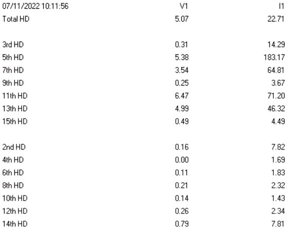
The original process equipment seems to be 2011 vintage (you indicate in your 9 Nov post that the motor has been in operation since 2011). This means it predates the IEEE 519-2014 edition - but I'm going to bet that the drive you are presently using does not. If that is the case - the TOTAL VOLTAGE HARMONIC (THD) limit is 5%, with no single harmonic (up to 151th) over 3%. Depending on the number of the current harmonic (3rd, 5th, 11th, 21st, etc.) the maximum allowable limit changes with the Isc/Iload (short-circuit current to load current) ratio; for the frequencies you're likely to be seeing, no single harmonic exceeds 12% and the TOTAL CURRENT HARMONIC (TDD) is likely to be less than 15%. From the data you provided, you're well outside this condition.
Having high harmonics can definitely lead to thermal stress in the windings. So can operating above the design power level for the speed (in part because the machine can have a difficult time properly cooling itself at slower shaft speeds). That is why a lot of variable speed motors use separately-powered fans for cooling, instead of shaft mounted fans (like a "standard" TEFC or TEAO construction.
You also mentioned seeing a temperature of 100 C - was this a TOTAL temperature, a RISE temperature, or something else? How was it measured, and on what part of the machine? PTC sensors are "on/off" devices - they can only tell you when you've passed a preset limit going in one direction or the other, not where you are below (or above) that limit).

Converting energy to motion for more than half a century
 
@Gluzchuk (Industrial),
My own calculations based on the harmonics data you provided tell me your motor can not take more than 60% of your motor capacity without overheating. The factor K I got is 1.678 and you have to reduce the motor load to 1/K ~ 60%. Perhaps, the rewinding job made the new motor impedance reinforce the harmonics from your VFD and made it larger, IMO.
Better still, use detuned filters to trap the harmonics. Choose a tuning order of 4.7 (your major harmonics is the 5th).
 
The harmonics table provided by the OP looks like the typical spectrum on the input line. So, there is no justification to calculate the motor derating by this as done by Parchie.
 
If the VFD is misfiring, it can be detected either with electric or vibration instrumentation.

Fluke's instructions for troubleshooting a VFD are here (electrical instrumentation)

Vibration Analysis Case Study 3 – Variable Frequency Drive Deterioration(vibration analysis).

Misfiring will often show up as torsional vibration (or coging at low speed).

These approaches will also detect a number of hard to troubleshoot motor defects.
 
Thank for your response,
The speed from the name plate is 1.500 rpm with 8 pole 50hz.
The speed of the motor could be 800 or 100 rpm depend on process.
Both motor have PTC thermistor already installed in them and they are working well.
About the PTC should have shut down the VFD, your are right, but the the temeperature is rise until limit but not reach it, I guess the winding would damage in funtion the time or the oldest motor shouldn´t work.
And the new motor trip the thermal overload protection so it is properly programed because it is on/off.
 
Our motor use separately-powered fan for cooling beacause it could have variable speed and It is working well too.
The motor is running at a steady rate and it is designed to use with the VFD.
Actually, we are doing the vibration analysis every month and it is ok.
 
O.M.G. Let's assume power proportional to speed squared (because that's easier to do in my head than power squared to speed cubed).

At 800 rpm, drive output frequency = (800/1500*50) = 26.7 Hz. The maximum allowed HP loading at that speed will be 114 HP.

Similarly, the frequency at 100 rpm will be 3.3 Hz. Max HP load at that speed will be 1.8 HP (which probably isn't enough to even break away from standstill).

Converting energy to motion for more than half a century
 
Power capability of a motor run from a VFD is not a squared relationship, it is direct. Torque remains the same, but because HP or motor kW is a mechanical representation of torque and speed, since the speed drops, the power drops proportionally. So because 1000RPM from a 1500RPM motor is 67% speed, the HP capability of the motor becomes 67%, so starting from a 400HP motor, it is now 267HP. For whatever that’s worth.

I’ll restate though that if the motor is BURNING OUT, then there is something not correct in the protection scheme. Don’t waste time looking for other obscure causes.


" We are all here on earth to help others; what on earth the others are here for I don't know." -- W. H. Auden
 
Status
Not open for further replies.
Back
Top