squeakychair
Mechanical
Hi everyone,
I would like some validation on my calculations of the required torque and power for a motor to drive a heavy but slow conveyor belt assembly. I feel that I may have underestimated these values significantly.
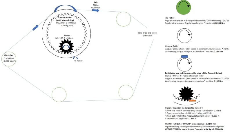
Method of driving: Motor pinion drives a large roller via a internal ring rack-and-pinion transmission, with the pinion acting as the only (driving) internal gear and the large roller acting as the (driven) ring gear.
System: This is a conveyor belt setup where the large Cement Roller (the driving pulley) drives the steel belt over a few idle steel rollers (driven pulleys). It depends on surface friction between the belt and the roller, so no chain & sprockets are involved. All idle rollers are hollow cylinders with cover plates, bolts, bearings and axial shafts attached to their sides.
Specifications
For convenience/privacy I'll leave out the roller configurations, and get to the behavior of the rollers immediately. I also approximate the pitch diameter of the cement roller as equal to its outer diameter (in contact with the belt). Instead of providing the mass of each roller, the moment of inertia about their rotating axis is given, which accounts for the mass distribution of the entire roller (including the bolts and plates etc.).
Motor pinion, the internal gear: M3, 10 teeth, 30 mm diameter [drives cement drum]
1 x Cement Roller, also the Ring Gear: M3, 300 teeth, 900 mm diameter; Inerta 100 kg m^2
10 x Idle Roller: 200mm diameter; Inertia 0.500 kg m^2
Belt: 500 kg, operating speed at 0.2 m/s (slow!)
Time to reach operating speed from rest: 5 seconds
My Approach
I only calculated the accelerating torque as I assumed that it was significantly larger than the continuous torque required to overcome bearing friction.
My end goal was to determine the tangential force on the pinion required to accelerate the belt to an operating speed of 0.2 m/s in 5 seconds. The tangential force on the pitch diameter of the Cement Roller is equal and opposite to that on the pinion. Three things contribute to the tangential force:
the torque to turn the Cement Roller from rest (Inertia of Cement Roller x Angular Acceleration of Cement Roller), divided by the diameter of the Cement Roller;
the torque required to the accelerate the belt from rest (Inertia of Belt x Angular Acceleration of Cement Roller), divided by the diameter of the Cement Roller;
and the torque required to turn each Idle Rollers from rest (Inertia of Idle Roller x Angular Acceleration of Idle Roller), divided by the diameter of the Idle Roller and multiplied by the number of Idle Rollers.
For 1 & 3, angular acceleration was found by dividing the angular velocity by 5 seconds; angular velocity was found by dividing the linear belt speed by the circumference of the Cement Roller or Idle Roller respectively.
For 2, I treated the belt as a point mass on the diameter of the Cement Roller, hence obtaining its moment of inertia using I = MR^2.
Final Calculations
Accelerating torque to move Cement Roller = 0.148 Nm; Tangential force contributed = 0.329 N
Belt Inertia = 101.25 kg m^2; Accelerating torque to move Belt = 0.150 Nm; Tangential force contributed = 0.333 N
Accelerating torque to move one Idle Roller = 0.00333 Nm; Tangential force contributed (for 10 rollers) = 0.333 N
Total tangential force experienced by Cement Roller = 0.996 N
... which is also the tangential force experienced by the Pinion.
Hence, motor torque provided to Pinion = 0.996N x Pinion pitch diameter (30mm) / 2 = 0.0149 Nm
Finally, motor power = torque x angular velocity = 0.0149 Nm x 0.222 rad/s = 0.00664 W
We can find the angular velocity of the motor pinion using the gear ratio between the Cement Roller (Ring Gear) and the Pinion.
Help! As you can see, the final power calculated is very small. Motors start at 100 W and above. I would appreciate any validation of my calculations, or feedback on more dynamic components to include. Thank you so much!
I would like some validation on my calculations of the required torque and power for a motor to drive a heavy but slow conveyor belt assembly. I feel that I may have underestimated these values significantly.
Method of driving: Motor pinion drives a large roller via a internal ring rack-and-pinion transmission, with the pinion acting as the only (driving) internal gear and the large roller acting as the (driven) ring gear.
System: This is a conveyor belt setup where the large Cement Roller (the driving pulley) drives the steel belt over a few idle steel rollers (driven pulleys). It depends on surface friction between the belt and the roller, so no chain & sprockets are involved. All idle rollers are hollow cylinders with cover plates, bolts, bearings and axial shafts attached to their sides.
Specifications
For convenience/privacy I'll leave out the roller configurations, and get to the behavior of the rollers immediately. I also approximate the pitch diameter of the cement roller as equal to its outer diameter (in contact with the belt). Instead of providing the mass of each roller, the moment of inertia about their rotating axis is given, which accounts for the mass distribution of the entire roller (including the bolts and plates etc.).
Motor pinion, the internal gear: M3, 10 teeth, 30 mm diameter [drives cement drum]
1 x Cement Roller, also the Ring Gear: M3, 300 teeth, 900 mm diameter; Inerta 100 kg m^2
10 x Idle Roller: 200mm diameter; Inertia 0.500 kg m^2
Belt: 500 kg, operating speed at 0.2 m/s (slow!)
Time to reach operating speed from rest: 5 seconds
My Approach
I only calculated the accelerating torque as I assumed that it was significantly larger than the continuous torque required to overcome bearing friction.
My end goal was to determine the tangential force on the pinion required to accelerate the belt to an operating speed of 0.2 m/s in 5 seconds. The tangential force on the pitch diameter of the Cement Roller is equal and opposite to that on the pinion. Three things contribute to the tangential force:
the torque to turn the Cement Roller from rest (Inertia of Cement Roller x Angular Acceleration of Cement Roller), divided by the diameter of the Cement Roller;
the torque required to the accelerate the belt from rest (Inertia of Belt x Angular Acceleration of Cement Roller), divided by the diameter of the Cement Roller;
and the torque required to turn each Idle Rollers from rest (Inertia of Idle Roller x Angular Acceleration of Idle Roller), divided by the diameter of the Idle Roller and multiplied by the number of Idle Rollers.
For 1 & 3, angular acceleration was found by dividing the angular velocity by 5 seconds; angular velocity was found by dividing the linear belt speed by the circumference of the Cement Roller or Idle Roller respectively.
For 2, I treated the belt as a point mass on the diameter of the Cement Roller, hence obtaining its moment of inertia using I = MR^2.
Final Calculations
Accelerating torque to move Cement Roller = 0.148 Nm; Tangential force contributed = 0.329 N
Belt Inertia = 101.25 kg m^2; Accelerating torque to move Belt = 0.150 Nm; Tangential force contributed = 0.333 N
Accelerating torque to move one Idle Roller = 0.00333 Nm; Tangential force contributed (for 10 rollers) = 0.333 N
Total tangential force experienced by Cement Roller = 0.996 N
... which is also the tangential force experienced by the Pinion.
Hence, motor torque provided to Pinion = 0.996N x Pinion pitch diameter (30mm) / 2 = 0.0149 Nm
Finally, motor power = torque x angular velocity = 0.0149 Nm x 0.222 rad/s = 0.00664 W
We can find the angular velocity of the motor pinion using the gear ratio between the Cement Roller (Ring Gear) and the Pinion.
Help! As you can see, the final power calculated is very small. Motors start at 100 W and above. I would appreciate any validation of my calculations, or feedback on more dynamic components to include. Thank you so much!