Eng-Tips is the largest engineering community on the Internet

Intelligent Work Forums for Engineering Professionals

  • Congratulations waross on being selected by the Tek-Tips community for having the most helpful posts in the forums last week. Way to Go!

Motor Starter Feeder - Control Schematics

Status
Not open for further replies.

NickParker

Electrical
Sep 1, 2017
396
0
16
NL
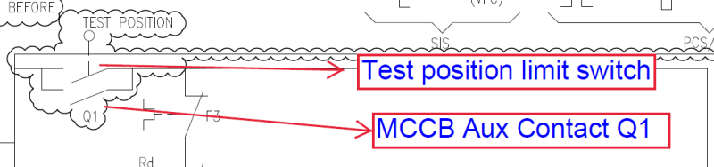
In the attached starter feeder control schematics, the control power to the starter is tapped from the line side of the circuit breaker. Interlock is made such that control power is unavailable when the breaker is off/trip.

So when the breaker trips -> control power unavailable -> contactor trips.

It seems that when the breaker trips, the contactor also trips. Is it desirable in the event of short circuit?
 
 https://files.engineering.com/getfile.aspx?folder=0d6473f4-c8e9-47bc-a2fa-31b3fd0bad83&file=Starter_feeder.pdf
Replies continue below

Recommended for you

The contactor takes a definite time to drop out and break contact. (Up to 100 milliseconds for small contactors. It depends.
The contactor does not start to drop out until the breaker has cleared.
That's the way it has been done for probably 100 years or more.
For some types of machines, there is a code requirement that the machine shall not automatically restart when power is restored after an outage.
There are safety concerns in that turning the breaker off removes all power in the starter enclosure.
There are exceptions for special cases.

Bill
--------------------
Ohm's law
Not just a good idea;
It's the LAW!
 
@ Waross, Can you please explain the safety concerns regarding the removal of control power in the starter enclosure when the breaker turns off
 
In a combination motor starter, or an MCC bucket, the breaker or switch must be turned off to release the door interlock.
That should remove all internal voltages for safety.
Feeding the control circuit from the circuit breaker, either directly or through a control transformer serves this purpose.
I have worked in plants where the control was from an external source. There was an auxiliary switch fitted to the disconnect linkage that disconnected the control circuit when the breaker or switch was opened.
In some applications, a warning label is attached to the starter door or cover:
WARNING MORE THAN ONE SOURCE OF CURRENT
Not all installations are code compliant.
Sometimes electricians get a shock from non code compliant control circuits.


Bill
--------------------
Ohm's law
Not just a good idea;
It's the LAW!
 
Dear Mr. NickParker (Electrical)
" ...the control power to the starter is tapped from the line side of the circuit breaker. Interlock is made such that control power is unavailable when the breaker is off/trip....It seems that when the breaker trips, the contactor also trips. Is it desirable in the event of short circuit? ...."
1. In the IEC world (IEC 60947-4-1), [a motor starter] is typically made up of i) a switching device (contactor) and ii) an overload protection device (OL). These i) and ii) MUST be coordinated with iii) a short-circuit protection device (SCPD)[e.g. MCB, MCCB or fuse]; a device capable of providing protection to i) and ii) being damaged by high short-circuit current. That is, the contactors and overloads are NOT designed to withstand the (short-circuit current) [which can be 20-50kA].
2. Complete coordination tables (acc. IEC 60947-4-1)are available from the manufacturers for i), ii) and iii) according to the rated operation voltage, motor power and the rated short-circuit current; classed into [Type 1 or Type 2] coordination.
3. a) Type 1: in short-circuit condition, the contactor or starter does not endanger persons nor installations and will not be able to then operate without being repaired or having parts replaced,
b) Type 2: in short-circuit condition, the contactor or starter does not endanger persons nor installations and will be able to operate afterwards. The risk of contacts light welding is acceptable.
Che Kuan Yau (Singapore)
 
Interlock is made such that control power is unavailable when the breaker is off/trip.

Unless I missed something, I don’t see that in your schematic actually. With the Control Transformer primary being tapped from the LINE side of the breaker, the breaker tripping will NOT drop out the contactor. That is not a good design in my opinion because it means that after a breaker trip event, as soon as someone recloses the breaker the motor could run and it might be unexpected, which is fraught with dangers.


" We are all here on earth to help others; what on earth the others are here for I don't know." -- W. H. Auden
 
Thanks Jeff. I missed that the control power was taken off ahead of the breaker.
That is probably a code violation and definitely a safety violation.
Years ago I worked in a mill that had all the control circuits fed from about three breakers in a lighting panel. This would be a code violation today.
The disconnect switch in each MCC bucket had an auxiliary switch that opened the control circuit when the disconnect switch was opened.
Unfortunately, do to a bad design, the auxiliary switch often DID NOT close the control circuit when the disconnect switch was closed.
That led to a few unfortunate incidents.
I am quite happy with the present practice of using control transformers fed from the load side of the breaker or disconnect in Combination starters and MCC buckets.

--------------------
Ohm's law
Not just a good idea;
It's the LAW!
 
@Jraef, Yeah the schematic representation could have been made better, see the below image

Test_position_limit_switch_vhntjj.png
 
Are you sure that that is not a circuit for a draw-out breaker? Test positions are common for draw-out breakers but not for Molded Case Circuit Breakers.

--------------------
Ohm's law
Not just a good idea;
It's the LAW!
 
I did miss the Q1 contact, thanks.

Bill, this is a typical diagram for an IEC style MCC, where the "buckets" have limit switches on the structure that are tied to a separate handle that, similar to a Draw Out Switchgear scheme here in NA, pulls the stabs off of the bus and put the bucket into a "test" position where the limit switches open the control circuit.

Nick,
MCC starter and feeder buckets here in North America are different, we don't typically have that feature available, hence the confusion from people based here. I have worked for EU based manufacturers and been exposed to both types, but that is somewhat rare.


" We are all here on earth to help others; what on earth the others are here for I don't know." -- W. H. Auden
 
Status
Not open for further replies.
Back
Top