MagneticFlux
Electrical
Greetings all,
I would like some opinions/suggestions on an issue being experienced with a VFD and motor.
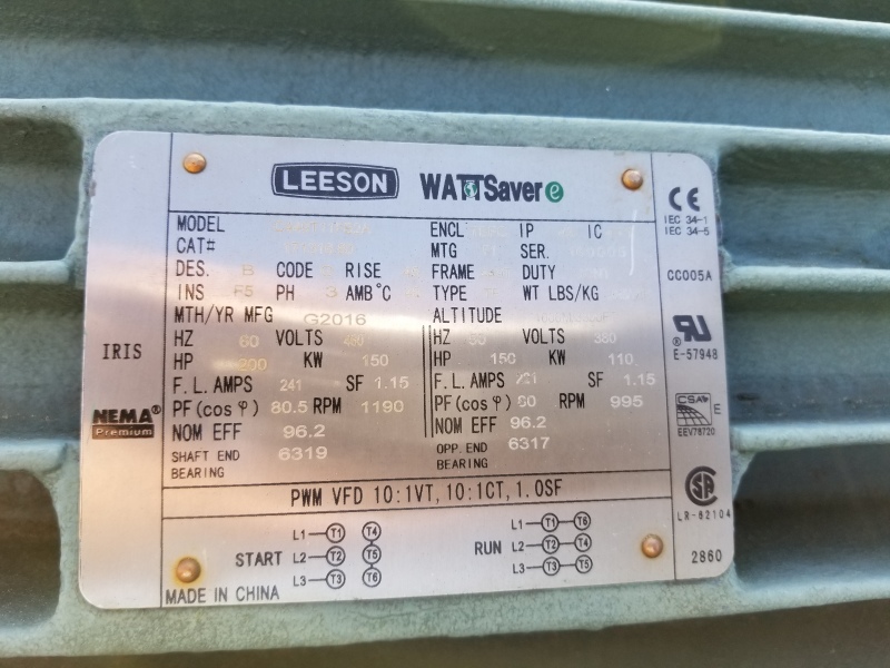
Motor Specs:
Volts 460
F.L. Amps 239
S. F Amps 275
RPM 1200
Hertz 60
HP 200
Duty CONTINUOUS
TYPE TD
Frame 447T
Serv. F. 1.15
Phase 3
Design B
Code G
Insul Class F
Eff 100% 96.2
Connection 6 Lead Star-Delta
Link
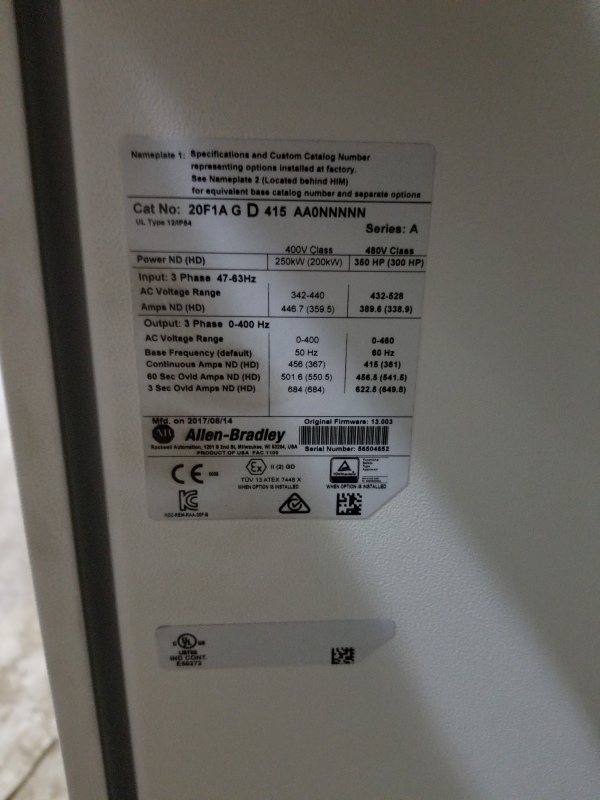
Drive Specs:
Product: Allen Bradley 23C-D460A103NNMANN
Description: PowerFlex 400, Fan & Pump Packaged Drive
Version Voltage Code 480 VAC, 3 PH
Output Current 460 Amps
Human Interface Module Fixed Keypad
Enclosure IP20 / Type 1
Version RS485
Frame Size H
Setup:
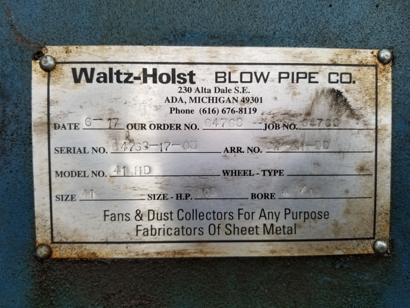
Motor is driving a P type fan via direct coupling
Motor connection = DELTA (connection has been verified twice)
Drive tuned and configured for 200HP motor, all settings default with exception to motor nameplate data, voltage input and auto-tune data.
Motor Data = (matches above info)
Voltage Input = 480 Volt
Auto-tune = calculated by VFD based on above info
Motor Control Mode = V/Hz
Application Mode = None, no PID inputs, being controlled via HMI
ISSUE: (Note that I am not performing the install/setup, I got involved because someone asked me to look into this).
The motor will not come up to full speed before O/C limit is reached. With frequency set-point at 60Hz: as the motor ramps up to speed (ramp time = 30 seconds), at +18HZ an over current alarm is indicated on HMI. Longer ramp times have no effect. The VFD will ramp up to ~18Hz and go into 'current trim mode' as this is highest frequency achievable before current output peaks at ~275 amps(SF amps). Adjusting the frequency beyond 18 Hz triggers O/C alarm.
Motor manufacturer recommends leaving the motor connected in delta and starting ATL to determine if this is a drive or motor issue. This was thought I had as well but Size 5 starters are not laying around like they used to be 20 years ago so, for the time being, that option is off the table. My thoughts are centered on drive parameter settings but the settings are as basic as they need to be for nominal operation. Any thoughts?
I would like some opinions/suggestions on an issue being experienced with a VFD and motor.
Motor Specs:
Volts 460
F.L. Amps 239
S. F Amps 275
RPM 1200
Hertz 60
HP 200
Duty CONTINUOUS
TYPE TD
Frame 447T
Serv. F. 1.15
Phase 3
Design B
Code G
Insul Class F
Eff 100% 96.2
Connection 6 Lead Star-Delta
Link
Drive Specs:
Product: Allen Bradley 23C-D460A103NNMANN
Description: PowerFlex 400, Fan & Pump Packaged Drive
Version Voltage Code 480 VAC, 3 PH
Output Current 460 Amps
Human Interface Module Fixed Keypad
Enclosure IP20 / Type 1
Version RS485
Frame Size H
Setup:
Motor is driving a P type fan via direct coupling
Motor connection = DELTA (connection has been verified twice)
Drive tuned and configured for 200HP motor, all settings default with exception to motor nameplate data, voltage input and auto-tune data.
Motor Data = (matches above info)
Voltage Input = 480 Volt
Auto-tune = calculated by VFD based on above info
Motor Control Mode = V/Hz
Application Mode = None, no PID inputs, being controlled via HMI
ISSUE: (Note that I am not performing the install/setup, I got involved because someone asked me to look into this).
The motor will not come up to full speed before O/C limit is reached. With frequency set-point at 60Hz: as the motor ramps up to speed (ramp time = 30 seconds), at +18HZ an over current alarm is indicated on HMI. Longer ramp times have no effect. The VFD will ramp up to ~18Hz and go into 'current trim mode' as this is highest frequency achievable before current output peaks at ~275 amps(SF amps). Adjusting the frequency beyond 18 Hz triggers O/C alarm.
Motor manufacturer recommends leaving the motor connected in delta and starting ATL to determine if this is a drive or motor issue. This was thought I had as well but Size 5 starters are not laying around like they used to be 20 years ago so, for the time being, that option is off the table. My thoughts are centered on drive parameter settings but the settings are as basic as they need to be for nominal operation. Any thoughts?
![[bigears]](/data/assets/smilies/bigears.gif "[bigears] [bigears]") . Regardless of the motors condition (new vs rewound), I have all ready suggested that it be uncoupled and ran. That was done, results; motor ran up to base speed, current about 25% of name plate (or at least that whats I am being told). In regard to the power transmission, I agree with your thinking that it may be undersized for direct coupling. There are setups currently on-site that are utilizing 200HP motors to drive fans that are half the size AND at higher speeds (1800RPM motor driving fan at ~2000RPM). I mentioned this while on-site and got the 'deer in the head lights' stare. I then recommend that the fan manufacturer review and verify the HP requirements; no feed back yet. If I provide specs on the fan, could you approximate the needed HP?
. Regardless of the motors condition (new vs rewound), I have all ready suggested that it be uncoupled and ran. That was done, results; motor ran up to base speed, current about 25% of name plate (or at least that whats I am being told). In regard to the power transmission, I agree with your thinking that it may be undersized for direct coupling. There are setups currently on-site that are utilizing 200HP motors to drive fans that are half the size AND at higher speeds (1800RPM motor driving fan at ~2000RPM). I mentioned this while on-site and got the 'deer in the head lights' stare. I then recommend that the fan manufacturer review and verify the HP requirements; no feed back yet. If I provide specs on the fan, could you approximate the needed HP?