Eng-Tips is the largest engineering community on the Internet

Intelligent Work Forums for Engineering Professionals

  • Congratulations waross on being selected by the Tek-Tips community for having the most helpful posts in the forums last week. Way to Go!

Motors in tandem 3

Status
Not open for further replies.

Guardiano

Electrical
Nov 11, 2008
118
0
0
MU
Hi,
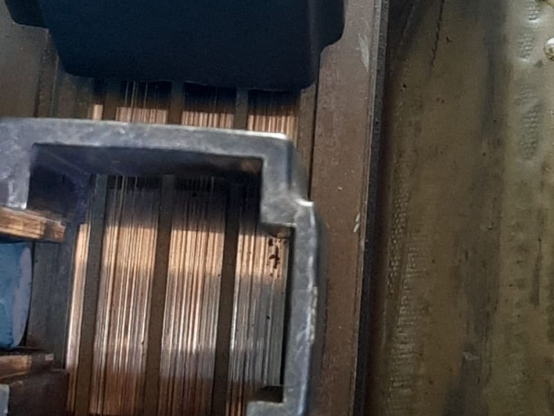
We have two 5 MW 6.6 k V wound motors driving a crusher in tandem. We have always been running the crusher with the two motors powered. Now because of load reduction, only one motor is powered and the powered electric motor drives both the load and the second motor. We noticed a very strange phenomenon on the slip ring of the unpowered motor. See attached picture. The commutator has started to wear out. It is worth pointing out that we have been operating like this for only a couple of days and the surface of the slip ring of the unpowered motor was initially very smooth. The slip ring of the powered motor is fine. The slip ring of the unpowered motor is shorted. What could cause the slip ring to wear out? Thanks for any inputs.
Guardiano
 
Replies continue below

Recommended for you

Thanks Edison. See picture.
image1_ygpkna.jpg
 
That's symptom of underloaded brushes and is a severe damage. The 3rd section on the extreme right seems to have blowholes. Also, the brush holder to be shifted axially to the right to ensure full seating of the brush.

The slipring has to be machined to remove the grooving before reuse. Machining might possibly remove the blowholes. If the motor is running idle, remove the brushes.

Muthu
 
Yup, good call by edison. Minimum current is required to maintain a proper film condition. I don't know the full reasons, but it reminds me of the similar phenomenon for certain switching electrical contacts where a minimum interrupt current is needed to wipe the contact of oxidation which can interfere with reliable operation.

See also threading damage shown here:
One of the listed causes is insufficient current.


=====================================
(2B)+(2B)' ?
 
Guardiano:
A commutator and a slip ring (also called a collector) are very different things. What you have here - for a wound rotor induction motor - is a slip ring / collector. The ring is designed to have spiral grooving (the three heavy dark areas exposed by the removal of the brush) to help dissipate heat and remove excess carbon material as the brush wears. The holder -as shown in the photo - is in the correct axial position for this ring.

Your difficulty lies in the fact that the unpowered motor has brushes riding in contact with the rings, with no current flow. The brushes are - most likely - a metal-graphite composition. If run lightly loaded (which is anywhere much below 70 A/in2 ( 0.1 A/mm2 ) will result in the phenomenon in the photo. The name of the phenomenon in its early stages is "threading" - a series of very fine lines running circumferentially around the shaft caused by the exchange of ring material into the brush, and then the trapped metal literally cutting the ring surface. As it gets worse, it progresses to "grooving" - a series of much heavier circumferential lines as seen in the photo.

The only way to correct this is to re-machine the ring surface to achieve a smooth finish. When doing so you may also have to re-cut both the spiral and the chamfer that is on the very edge of the spiral (e.g. break the sharp edge left by the spiral tool). Be sure you have enough remaining ring material to allow you to accomplish both the surface cleanup and the spiral depth increase without compromising mechanical integrity. Once you've figured out how much smaller you have to make the ring outside diameter (as a rough estimate, I'd say it looks to be around 0.040 inch = 1 mm per side), you need to also check that the resulting distance between the holder and ring surface is not too great. This distance should be in the 2-3 mm range (0.080-0.120 inch). You may be able to modify the radial position of the holder on its support - or you may have to modify the support itself. In either case, both the ring finish and holder location must be corrected prior to energizing this machine.

For future: if these machines are really mechanically connected in tandem (e.g. something akin to a "through" shaft or, in electrical terms, a "series' connection) then you have two choices if your load profile continues to vary. One is to operate both machines at significantly reduced load - which might increase brush wear on each unit, but should save the rings from this kind of damage. The other is to investigate the possibility of using a lifting mechanism so you can readily lift or replace whole brush sets (on the coasting unit) as the load changes and therefore operate only one unit at a time. To keep overall wear and tear fairly uniform between the units, you'd have to install the mechanism on both, as you'd want to sometimes use one unit as the "driver" and sometimes the other.
 
> A commutator and a slip ring (also called a collector) are very different things.

I understand that's a correction to op's terminology. I need to mention the photo I posted was commutators. Slip rings and commutators share a lot in common and are sometimes described together like here... although the latter link doesn't show threading... hence my earlier link to the commutator document which includes a photo of threading resembling op's.


=====================================
(2B)+(2B)' ?
 
Status
Not open for further replies.
Back
Top