Eng-Tips is the largest engineering community on the Internet

Intelligent Work Forums for Engineering Professionals

MSC Nastran - Help in Modeling this Setup

Status
Not open for further replies.

Burner2k

Aerospace
Jun 13, 2015
193
0
0
IN
Hello,
I need some help in trouble shooting/modeling this setup. I am using MSC Nastran as solver.

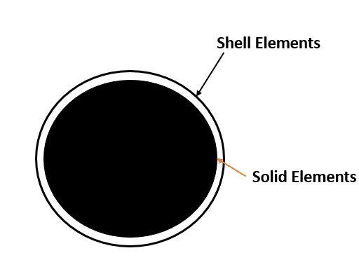
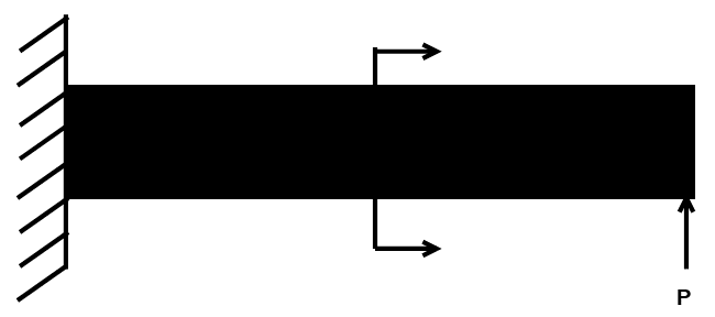
The setup is shown below with the cross-section shows the arrangement of the beam.

Beam_y6ox4a.png
Beam_CS_nd4ucy.png


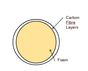
The outer skin is made from Carbon Fiber laminate and the core is made of foam.

I have modeled the the beam as a combination of PCOMP (CQUAD)-PSOLID (CHEXA)-PCOMP (CQUAD). The PCOMP is setup as orthotropic material (MAT8) with plies and PSOLID is configured as an isotropic material (MAT1).

FEA_kd4erq.png


We have test data (only deflections) for the beam. But when we run our FE, the deflections are coming quite high compared to test (around 35% higher). Trying to figure our where I am going wrong. One more note, there are not DOF coupling elements between PCOMP & PSOLID. No RBE2s or any kind of contact. We have tried with glue contact and we are finding that it making the model more stiffer. I am not sure if we need any kind of DOF coupling element but the deformation looks OK (transverse bending).

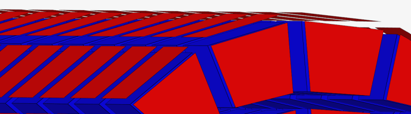
The shell elements were extracted from Hexa elements faces, so there is no issue of node connectivity or equivalencing.

Before figuring out the material properties, we want to make sure our modeling methodology is correct. I would appreciate any pointers from experienced people on how to proceed.
 
Replies continue below

Recommended for you

if the section is constant, them we know the solution for a propped cantilever. From your test data you can deduce the effective EI of the section.

"Hoffen wir mal, dass alles gut geht !"
General Paulus, Nov 1942, outside Stalingrad after the launch of Operation Uranus.
 
You modelled as a round beam? Or just shells on top and bottom of rectangular solid?
And why bother modelling the foam?
Why would you not use common nodes between the composite and foam? Why mess with glueing, etc?
And what did you use fir material properties? - those will affect deflection.
 
Firstly,
Thanks for replying folks.

The objective is to establish methodology of FE modelling using a simple circular sandwich construction beam (for which we have test data) before moving to more complex cross-section (airfoils).

The material properties are defined as follows:
1. For Composite: Fiber properties defined on a MAT8 card.
2. For Foam: Isotropic Properties defined on MAT1 Card

Screenshot_2023-10-16_122225_hqikti.png


The PSHELL elements were extracted from PSOLID faces...thus there is node-node connectivity. I want to figure out why our FE model is softer compared to test data. The test data does not include any strain values only tip deflection values.
 
Basically, I am thinking that post-curing, there is quite a bit of resin uptake in the foam core which is making the foam more stiffer than what the values on the manufacturer's sheet gives. Of course, the manufacturer's data sheets gives values of mechanical properties carried out on actual foam (not resin soaked).

Is there any empirical way of calculating or scaling mechanical properties based on foam & resin type? Of course, one can always adjust by scaling up or down the material properties of foam to match test values but perhaps, then it has to be done each time we have a different construction or shape!
 
"The PSHELL elements were extracted from PSOLID faces...thus there is node-node connectivity."

can you expand on what you mean by this ? why wouldn't the shells and solids share nodes ?

If there is something happening during the cure cycle, that could be a problem. but then maybe you need a glue element between them ?

what job is the foam doing for you ?

"Hoffen wir mal, dass alles gut geht !"
General Paulus, Nov 1942, outside Stalingrad after the launch of Operation Uranus.
 
What is going near the end of beam where load is applied? Maybe test team glued some metal plate to the end of beam and push into this plate and if FEA model beam don`t has this plate. For thick beams this may result in different behavior.
mceclip0-6350e7e1b47ab_mzgqtg.png


UPD. Do you use linear or nonlinear solver? If deflections are big than this problem may be geometrically nonlinear. Linear solution usually overestimates displacements when problem becomes geometrically nonlinear.
 
One thing I did not specify explicitly was that there is no gap in the elements between PSHELL & PSOLID. What I have shown in the cross-section images are exploded view for clarity. In the actual model, the PSHELL elements just lie (NO OFFSET) on top of PSOLID elements/faces & thus ensuring node-node connectivity.

In the image below, the blue elements are PSOLID & Red ones are PSHELL. The elements have been shrunk visually for clarity purposes but PSHELL are lying on top of PSOLID.

Screenshot_2023-10-17_084111_yrh31f.png


karachun, we thought about modelling in our FE the support plate to which beam is attached. Perhaps we will need to consider that.
 
by "node tp node connectivity" between the shells and the foam, you mean that they have common nodes, right ? the shell nodes are the foam nodes, yes?

is the foam bonded to the shells ? (I'd think so) is this a rigid or flexible bond ? is there something you could see under test too check this ?
if elastic, then you'd need two sets of nodes with a CBUSH between them ... or something like.

"Hoffen wir mal, dass alles gut geht !"
General Paulus, Nov 1942, outside Stalingrad after the launch of Operation Uranus.
 
RB1957,
Yes, the shells & foam (solid elements) share common nodes.

If you are asking, are we using bonded contacts between shells & foam (solid elements), the answer is NO. Since most of the load transfer between shell & solid elements happen axially, we thought DOF compatibility will be maintained. Further, in our FE model, if we look at the deflections, they are matching the expected shapes i.e. typical beam deflection and we are not getting any rigid body errors.

> is there something you could see under test too check this ?
Not sure if you meant by this...could you please elaborate further?
 
"surely" the foam is bonded to the skin ? Sure you can model with common nodes (and make the connection rigid) but then that may (will?) affect the accuracy of your model.

What job is the foam doing ? why is it there ? why fill a wing section with foam (that's what you'll do on the real design ?) ? The real wing will have distributed out-of-plane loads and may (will?) need support out-of-plane ??

"> is there something you could see under test too check this ?
Not sure if you meant by this...could you please elaborate further?"
is there something you can determine from your testing to verify the stiffness of the "bonding" ?

"Hoffen wir mal, dass alles gut geht !"
General Paulus, Nov 1942, outside Stalingrad after the launch of Operation Uranus.
 
I see one glaring issue you haven't addressed yet: why are you assuming no slippage between the laminate shell and the foam? Unless you have mechanical connectors or experimental evidence of the shear connection required to make the foam and laminate a composite section, there is no reason to assume that is the case.

What happens if you model the beam as an equivalent section (equivalent EI, GA by summing up contributions of slices along the vertical axis in the cross-section) and compute the displacement with elementary shear-deformable beam theory (tip load should be simple)? Results still off?

If the dimensions are as shown in your sketch (height-to-length ratio of five or so) and the displacement is more than 10-20% of the section depth, there might be geometric stiffening occurring during in the test (as already mentioned in this thread) which a linear analysis does not capture.
 
First, use of common nodes for the shell and solid elements is perfectly fine. Assuming no delaminations.

But, please post a photo of the actual beam and test setup you are attempting to correlate to. Without that all we can do is guess at things. There are a LOT of reality vs model issues that likely need to be sorted out.

 
Firstly, I'd like to thank all the people who helped especially ones who suggested that complete test setup needs to be included in FE Model. We did that...especially the parts which we think was contributing to rigidity and the results were great. We are getting good correlation (around 10%) between our test results & the FEA results. We are looking in to improving this correlation.
 
Status
Not open for further replies.
Back
Top