Eng-Tips is the largest engineering community on the Internet

Intelligent Work Forums for Engineering Professionals

Multiple Relays Sharing Same CT 1

Status
Not open for further replies.

rockman7892

Electrical
Apr 7, 2008
1,147
0
0
US
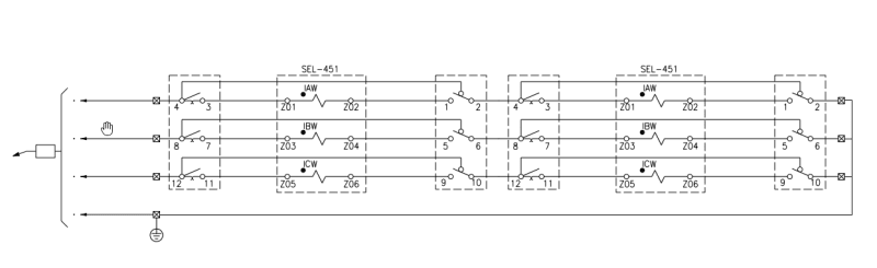
I have a situation where we need to connect (2) SEL-787 relays to the same CT. These are two primary feeds to a transformer (through an MTS) that are sharing the same secondary CT. Therefore there are two parallel overlapping differential zones with CT’a on each feeder and secondary CT driving (2) relays (one on each side)

The (2) relays are connected in series off of each single CT. What happens if the first relay in series fails or is de-energized? Will will that interrupt current flow to 2nd relay or does current continue to flow through 1st relay even though it is off?

Any other considerations or challenges in this arrangement from those that have had experience?
 
Replies continue below

Recommended for you

There is no issue with putting two relays in series on the same set of CTs. Even if the relay processor fails, the CT circuit will not be interrupted.
 
The two relays can be connected in series (not in parallel) to share a common CT winding. It is an industry practice.
In Oder to facilitate to isolate one relay for maintenance etc you have to wire two FT switches correctly so that
even one relay is isolated from one FT switch, the ct secondary will still be connected through the second FT switch
to the second relay. It is also a common industry practice.
 
Dear Mr. rockman7892 (Electrical)(OP)18 Aug 22 02:41
"...The (2) relays are connected in series off of each single CT... What happens if the first relay in series fails or is de-energized? Will that interrupt current flow to 2nd relay or does current continue to flow through 1st relay even though it is off?..."
1. It is correct to connect two relays in Series; irrespective of their different set (trip) values. Relay X trip set value at say x A , relay Y can be set at any value y, where x < = or > y. No problem.
1.1 When the CT secondary current > x , but < y; only relay X operates, if x is < y.
2. FYI: When any relay X or Y current coil is open circuited or any breakage along the current loop; both relays X and Y will NOT operate. This is equal to open CT secondary. Danger of over voltage, which may result to insulation break-down.
Che Kuan Yau (Singapore).
 
Thanks for the responses.

I’m trying to picture how the two FT switches would need to be wired in order to allow removal of one of the relays without interrupting circuit.

Can anyone help explain/describe so that I can visualize?

Thank You
 
Assume FT #1 has A Ph current on pole D & E (fairly std). Ia+ comes into E and out D. From FT #1 to 2, FT-1 D goes to FT#2 E and so on.

You should have a sticker or a note that if you plug in a Doble relay test set that is already connected to FT paddle and Doble is plugged in to remove the connection to the Doble before inserting the test paddle. The Doble current sources have their common neutral connection grounded and it may cause a misop of the down stream relay if the procedure is not followed. I scratched my head a few times trying to understand how this could happen, but apparently it does. I've seen those same caution signs in several different utilities in the US.
 
thermionic1

Thanks for the explanation that makes sense now. Essentially each test switch is just shoring out the CT input at its respective relay but allowing current to continue through to next. FT switch is esentially putting a jumper around relay input.

 
One more thing, as I see this from time to time. The Odd numbered terminals on the test switch go to the relay and the even numbered to the system. If not wired this way, the test paddles that are designed to work with FT are useless.
 
rockman7892 said:
I’m trying to picture how the two FT switches would need to be wired in order to allow removal of one of the relays without interrupting circuit.
Here is an example of 2 relays in series with FT test switches:
CT_circuit_2_relays_b2tfmx.png
 
Modern microprocessor relays pass the current over a very small impedance and measure the voltage. The relay can be unenergized and current is still going to flow through it provided its input limits were never exceeded, which I have never heard of happening.
 
Status
Not open for further replies.
Back
Top