Continue to Site

Eng-Tips is the largest engineering community on the Internet

Intelligent Work Forums for Engineering Professionals

  • Congratulations SDETERS on being selected by the Eng-Tips community for having the most helpful posts in the forums last week. Way to Go!

Multiple Welded Nozzles on B16.5 Blind Flange

Status
Not open for further replies.

TiCl4

Chemical
May 1, 2019
631
I have a situation that is a bit unusual. I have a need to weld two 3" nozzles onto a 24" B16.5 blind flange. The sketch is below; the design intent is to provide an enlarged portion of piping that would allow liquid monomer droplets that condense in the incoming stream drop out into the bottom portion of piping. Both nozzles are at the top to avoid horizontal runs, which would tend to collect droplets, which would polymerize and plug the pipe. The amount of liquid is minimal (drops per hour), but present a long-term plug hazard that must be dealt with.

Nothing in B16.5 that I've read details multiple nozzle locations on a blind. As such, I think this would be a non-standard part that needs detailed calculation. Not being a mechanical guy myself, I've come for help and guidance.

ASME B31.3, which would be used for this construction, does detail a procedure to check if branch connection reinforcement is needed. I am wondering if there is a similar calculation to be made for the blind to check the pressure/temperature rating. Again, this is a 24" blind (assuming class 150 right now) with a pressure rating (hopefully) of 150 psig.

Can anyone point me in the right direction to applicable codes or calculations for this?
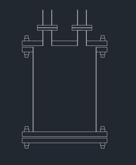
Knockout_Pot_Sketch_go4dji.png
 
Replies continue below

Recommended for you

We've been here many times and this is an example of one such query
Basically you don't have an ASME B16.5 flange any more.

Holes like this need to be looked at under ASME VIII div 1 appendix 2

HOWEVER - this usually means a much thicker flange than a "standard" blind flange or maybe one clas sup, so say a class 600 flange and blind for a system normally using class 300 flanges.

B31.3 is for pipe, not bland flanges.

Is this being used as a small pressure vessel? Designing it as a pipe might be a bit "naughty", but I've seen it done.

but it is a convoluted mess that no ones has clearly defined.

what sort of pressures are we talking here?

Remember - More details = better answers
Also: If you get a response it's polite to respond to it.
 
LI,

Operating pressure is actually under very slight vacuum, and is being used as an enlarged drip leg, if you will, in the piping to remove liquid droplets. This is downstream of a reactor/condenser system, and the worst-case scenario is this experiences full reactor pressure in a runaway event. The reactor itself is protected at 15 psig with a MAWP of 50 psig.

The pipe spool itself would be constructed to B31.3 - 24" w/ SO flanges. There need to be quite a few of these made, and I wanted to avoid the cost/headache of specifying and maintaining a bunch of tiny (~50 gal or smaller) pressure vessels. The 150 psig rating was simply to match the rest of the piping system, but it could be made lower to match reactor pressure rating.

If necessary, we could make two 3" branch connections off the sides of this pipe at an angle so that all components could be constructed with B31.3, we would avoid horizontal piping, and we wouldn't need to do anything "odd" or "naughty". This would take up more room, but

To go down the ASME VIII rabbit trail for the moment: To make this flange with a slip-on, am I right in interpreting Figure 2-4 in Section VIII Appendix 2 that a SO flange would be characterized in figure 3 (or 3A)?

Lastly, I guess we could also purchase a 3" flanged wye, route both pipes into the wye, and use the top flange as a reducing flange to ensure the B16.5 flange remains as such. That might be the best solution, as B16.5 has provisions for making a reducing flange. According to B16.5 table 6, a reducing 24" blind needs to be hubbed only if the outlet is 4" or greater. Am I reading that correctly?
 
TiCl4,

I agree that you can use B 31.3 to design this thing. Lowering the design pressure might make it easier to get the amended blind flange through an ASME VIII design check.

I don't use ASME VIII enough to have a copy, but if you copy in that figure we might be able to judge.

Yes a 24" flange can have a 3 1/2" or smaller tapping without needing a hubbed fitting.

Is there a reason your 24" pipe needs to be vertical and not horizontal?

There's an ongoing debate about whether the hole int he blind needs to be in the centre or not, but it looks better if nothing else....

Remember - More details = better answers
Also: If you get a response it's polite to respond to it.
 
LittleInch said:
Is there a reason your 24" pipe needs to be vertical and not horizontal?

There is no specific reason. The footprint is a bit smaller on the vertical. It's not shown in the sketch, but I intend on putting a bottom valve on the bottom flange or near the bottom of the pipe to provided periodic draining access. This will also have a very dilute sodium hydroxide solution in the bottom to hydrolyze the monomers, preventing them from reacting and forming "patty cakes" that would plug the drain. If it were on its side, it would need to be saddled. On the other hand, when horizontal the end flanges could be removed for in-place pressure washing when needed.

That brings up a point, though - could this rest on the concrete floor with no supports? The lower flange bolts would bear the weight of the construction.


Link to an online pic of the ASME VIII figure referenced (
 
Status
Not open for further replies.

Part and Inventory Search

Sponsor