Continue to Site

Eng-Tips is the largest engineering community on the Internet

Intelligent Work Forums for Engineering Professionals

  • Congratulations KootK on being selected by the Eng-Tips community for having the most helpful posts in the forums last week. Way to Go!

Mutilated Worm Drive for Intermittent Cam 5

vne147

Mechanical
Dec 5, 2024
12
Hello everyone. Mods, if you think there is a more appropriate forum for this question, please let me know. And thank you in advance to anyone who can provide some advice.

I’m working on developing a machine. This machine will have an output gear that will turn while the machine is in operation, and it will make one complete revolution per actuation of the machine. At about the 330° point in its rotation I need this output gear to turn a cam one complete revolution. The cam needs to be intermittent though. I can’t have it turning continuously along with the output gear. The cam needs to do nothing for almost the entire time until the output gear gets to about 330°. Then it will turn once, and just sit there again until the next cycle. Also, once the output gear gets to the point where it's time to turn the cam, I need that cam to turn as fast as practically possible.

So, the solution I came up with was to use a worm drive. The worm gear is mutilated with only a single tooth remaining, and the worm is offset so the single tooth on the worm gear will only mesh with a single turn on the worm. I attached a short animation with several angles to show what I’m talking about.

There are tons of mutilated gear examples I’ve seen, but very few with a worm drive, and none that I’ve seen with only a single tooth. So, this leads me to believe that maybe this isn’t the best solution, or it won’t work for some reason. Can you share your thoughts? How would you solve this problem? I’m not a mechanical engineer. Maybe there is a simpler solution. I just don’t know.

Thanks again.


View attachment WormGearExample.mp4
 
Replies continue below

Recommended for you

how big is your system? the amount of friction encountered by both worm and the single tooth gear will be an issue I can see. it may not be as smooth as in the simulation you did.
 
how big is your system? the amount of friction encountered by both worm and the single tooth gear will be an issue I can see. it may not be as smooth as in the simulation you did.
Hello, BEMPE16524. Thanks for your question.

If you're asking about physical size, the mutilated worm gear has a pitch diameter of 80mm and the worm has a pitch diameter of 16mm. It's an 80:1 worm drive.

If you're asking about how big in terms of loads, I haven't figured that out yet. But the loads will be relatively small. The pushrod at the bottom that follows the cam will drive a blade that will require less than 10lbs to make the cut. So overall there are no substantial loads that the system will see. I know" substantial" is a relative term though.

You're point about friction is well taken. I'm not too concerned about how smoothly the cam operates as long as it rotates when I want it to and as quickly as possible.

Can you think of any better ways to accomplish what I need to do?

Thanks.
 
vne147,

Read up on Geneva mechanisms.
Hello, drawoh.

Thanks for your suggestion. I'm familiar with Geneva mechanisms. I sort of already explored that as an option, but maybe you're thinking of it differently than me. I'm assuming your idea is that I could replace the mutilated worm gear in my simulation with the drive wheel portion of the Geneva mechanism, which would advance the driven wheel by 1 slot per cycle of the machine, which I could then use to rotate the cam one complete revolution through some combination of gearing.

In the animation I attached to my original post, the mutilated worm rotates through 4.5° (360/80) to rotate the cam at the bottom one complete turn. That's "fast" enough for my purposes (although even faster would be better). So, for me to swap everything over to a Geneva mechanism in the way that I think you're suggesting, I wouldn't want the driven wheel to need to rotate much more than about 4.5° to advance the driven wheel by 1 slot. I couldn't really figure out a combination of geometry that made that possible in the space I have to work with.

Maybe there is some clever variation of Geneva drive that I'm unaware of, or maybe you're thinking of something different.

Thoughts?
 
Last edited:
Describe what you are trying to accomplish in detail, listing all your requirements. What are you cutting, how, and why? Your design will not work. You cannot drive a worm gear backwards as you show. It seems you are trying to do what a punch press does, but you must have some other goal that you have not told us.
 
Last edited:
Describe what you are trying to accomplish in detail listing all your requirements. What are you cutting, how, and why? Your design will not work. You cannot drive a worm gear backwards as you show.
Hello Compositepro. Thanks for the input. I cannot share the level of detail you're requesting because what I'm cutting, how, and why is part of something for which we are seeking patent protection. While I agree that more information is generally better than less information, my question here is intended solely to solicit opinions on the best ways to rotate the cam as quickly as possible, with as little rotation of the mutilated worm gear as possible.

Maybe I'm missing something, but I'm not following you about driving the worm gear backwards. Are you saying that the worm won't rotate in the direction shown? Or are you saying that it won't work when the worm is the driven element?

Thanks.
 
A worm wheel is a partial helical thread wrapped around a disk; the mating feature (worm gear) is a screw thread. As a result the interaction responds very similarly to pushing on a nut on a screw thread to drive the screw. If a screw with a similar helical angle isn't going to be driven by a mating nut, the worm gear won't be driven by worm wheel; the situation you are counting on here.

I can see you are looking for a long dwell and then a very high amplification of the rotation. Maybe more than one tooth on the wheel and step-up involute gears to a bevel gear set to change the direction.
 
A worm wheel is a partial helical thread wrapped around a disk; the mating feature (worm gear) is a screw thread. As a result the interaction responds very similarly to pushing on a nut on a screw thread to drive the screw. If a screw with a similar helical angle isn't going to be driven by a mating nut, the worm gear won't be driven by worm wheel; the situation you are counting on here.

OK. This makes sense to me. So at least for the parts I have chosen so far (single start worm and 80:1 ratio) it'll be nearly impossible to backdrive the worm. Maybe if I went to a worm with 2 or 4 starts it might become more "backdrivable", but then I'd need that much more rotation of the mutilated worm gear to rotate the worm one revolution, which defeats the purpose.

I can see you are looking for a long dwell and then a very high amplification of the rotation.

I wish I could have stated it that clearly from the start. This is exactly what I'm looking to do.

Maybe more than one tooth on the wheel and step-up involute gears to a bevel gear set to change the direction.

If I'm understanding you correctly, I already sort of tried this. Basically, instead of the mutilated worm gear I'd have a mutilated involute gear which would drive a smaller involute gear, which would drive a bevel or miter gear set for the 90° change in direction. If that's not what you meant, please let me know.

The issue that I ran into with that approach was that I could only achieve a ratio of 10:1, which wasn't enough amplification of the rotation for my application. I make that 10:1 statement with the caveats of only single stage amplification, and I was looking only at off the shelf parts available from McMaster-Carr. Just for cost considerations I'm trying to keep the part count as low as possible, and I'm also trying to avoid having to get custom gears machined for the prototype. That's what drove me towards what seemed like an elegant 2 part solution with the worm set. Now that I understand the limitations with that, maybe I'll revisit my previous approach.

Thanks.
 
OP
Not enough info to make a suggestion.
The described will not work.
Suggest a cam mechanism.

Reason : to my under standing a worn wheel
Requires driven by the worm. And not by the worm wheel. As said before can nor be back driven
 
OP
Not enough info to make a suggestion.

Thanks for your input, but I disagree. Two people have already made suggestions and others including yourself have told me why what I came up with wouldn't work. My goal was to start a discussion where people could share their thoughts on my solution and any ideas they might have about how they would solve the problem themselves. I think I've provided enough information for that purpose. I'm not looking for a detailed design review or for someone to provide me with a complete solution. I really just wanted to hear a few ideas from knowledgeable people that would hopefully point me in the right direction. I feel like multiple people have helped me with that so far, and I continue to welcome to the discussion anyone else with any ideas to share.

Thank you.
 
I suggest you buy a cheap small worm drive and try driving the pinion using the worm gear. In my experience it simply won't move. Friction is simply too great going in the 'wrong' direction. Worm reductions have ~25% friction loss going in the right direction, FWIW.

Any reason you're not considering a stepper motor?

Thanks for the suggestion about testing the worm. I think enough people have voiced their feelings about my initial idea that I've been convinced to try something else. I haven't 100% given up on it yet though. I found this worm drive that I could possibly make work. Also, the last mechanism shown here at about 4:25 has some interesting possibilities. They both still seem to have the same basic problem as my original idea but potentially would be more easily back driven.

If I do have to abandon the idea completely though, I think I can achieve what I'm after (long dwell and high amplification of the cam rotation) using a two or three stage gear train where at least one of the gears will be a partial gear. The multiple stages can get me the amplification I need so that the cam rotates fast enough when I need it to, and the partial gear or gears will give me the dwell time. It just isn't as attractive to me because of the increased part count. Also, that final stage gear will be going pretty fast. If it's a partial gear like I think it would have to be it'll hit the teeth of whatever smaller gear it meshes with pretty hard when it comes around. There might still be a better way. I'm burning a lot of brain cells trying to find a cleaner solution.

In answer to your question about the stepper motor, one of the requirements is that it be a purely mechanical device that doesn't require electrical power. I would have been a pretty good solution otherwise.

Thanks for your help.
 
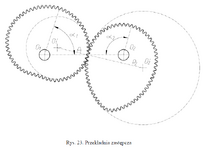
Just a thought: a non-circular gear set, similar to the one below, possibly designed for a bigger surge. O2 would be the driving gear.
https://prozamet.pl/galeria/si23.jpg
ra.png
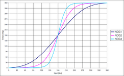
Put a number of such Non-circular gear sets in a serial arrangement to get more surge:
ncgs2.png
 
Last edited:
Maybe this.
Thanks for that video. I think I'm going to have to go to a partial gear arrangement something like what's shown there, but with at least two stages. I'm going to model a few possibilities and see if it works.
 
Just a thought: a non-circular gear set, similar to the one below, possibly designed for a bigger surge. O2 would be the driving gear.
https://prozamet.pl/galeria/si23.jpg
View attachment 2314
Put a number of such Non-circular gear sets in a serial arrangement to get more surge:
View attachment 2320
Wow. I hadn't considered this. So, the pitch diameter and therefore the gear ratio varies depending on where each gear is in its rotation. Do you happen to know any real-world applications of this type of arrangement? I like the idea, but it seems like it'll be expensive to manufacture.

Thanks!
 
Thanks for the suggestion about testing the worm. I think enough people have voiced their feelings about my initial idea that I've been convinced to try something else. I haven't 100% given up on it yet though.
You are comparing feelings against real-world experience. Not comparable.

As I say occasionally, physics does not give a f&*k how we feel.
 
You are comparing feelings against real-world experience. Not comparable.

As I say occasionally, physics does not give a f&*k how we feel.
Speaking as somebody with a degree in Physics, I agree that feelings aren't part of the equation. Maybe I could have phrased that better. How about this?

I think enough people have voiced their feelings real-world experience and apathetical nature of physics based recommendations about my initial idea that I've been convinced to try something else.​

I'm not sure about the grammar though. That was never my strongest subject.
 
Thanks for your input, but I disagree. Two people have already made suggestions and others including yourself have told me why what I came up with wouldn't work. My goal was to start a discussion where people could share their thoughts on my solution and any ideas they might have about how they would solve the problem themselves. I think I've provided enough information for that purpose. I'm not looking for a detailed design review or for someone to provide me with a complete solution. I really just wanted to hear a few ideas from knowledgeable people that would hopefully point me in the right direction. I feel like multiple people have helped me with that so far, and I continue to welcome to the discussion anyone else with any ideas to share.

Thank you.
Your welcome
An other approach may be a sector spur gear driven by a DC direct drive motor. Driving a gear wheel.
 

Part and Inventory Search

Sponsor