Eng-Tips is the largest engineering community on the Internet

Intelligent Work Forums for Engineering Professionals

MV cables (IEC)

Status
Not open for further replies.

mastergate

Electrical
Apr 22, 2011
40
0
0
MA
Dear all

I need your help for 2 issues :

1/ To order MV cables, please advise how to specify short circuit withstand capacity on cable metallic screen.
What I have at this stage, is the preliminary calculation of max short circuit value (for example 40kA @ 10kV level) which I use in equipement and cable (core) selection.


2/ For interconnection between 2 substations, is it mandatory to provide a separate MV cable for equipotential earthing?
for example, for a feeder with 2c x 1x300 mm2 per phase (Copper core, XLPE insul, 12/20kV). Do I have to foeresee a separate PE cable (of 1x300 mm2 ?) or are the cables' metallic screens sufficient for this purpose?


Thank you.
 
Replies continue below

Recommended for you

Howdy Mastergate,

1) There is no short-circuit rating for the shield on a MV cable. Should the shield ever see 40kA, it will be toast (ie vaporize). Some cable manufacturers will let you spec the overlap and thickness of the tape, but the tape is never expected to carry the any fault current. What are the particulars of the cable that you are considering? (ie single conductor, three conductor, concentric neutral, metal-clad, non-armoured, type TECK or type CLX, etc)

2)If I understand your situation; these two substations at the same industrial facility and are the connected via the MV cable? It would be very common, within an industrial facility, to tie the two grid systems together with (say) two runs of 4/0awg copper ground conductor. The required size is likely defined in your local codes [ie NEC (NFPA-70), CEC (CSA), etc ]
If the feeders are overhead in tray or cable-bus, then the ground conductors should be insulated. If the feeders are underground, either direct-buried or in a duct-bank, then the ground conductors should be bare.
The shields of the cable are not adequate for grounding of anything.
Since this is a MV installation, someone will be undertaking a touch/step/station rise calculation, correct?

Regards,
GG


"Wish I didn't know now what I didn't know then." -- Bob Seger
 
If you need high current capacity for neutral/ground current you run a separate ground conductor of you use cable with a concentric neutral. Assume the shield has a fault rating of 0A.
 
The cable screen is rated for whatever current/time it says in the cable specification. There seems to have been a presumption made that the screen is tape. You can specify copper wire screens with whatever fault rating you require. However if your earth fault level is really anywhere near 40kA, for safety's sake you should be looking to reduce it.

Regards
Marmite
 
Hi Marmite,
The OP did not state that he has 40kA of ground-fault current, but rather 40kA of short-circuit current. I trust that the OP will be installing a NGR to limit the ground-fault current; one can only hope. I agree with you that 40kA is one heck of a lot of fault-current at 10kV. (ie 40kA implies a xfmr size in the 40MVA range.)

In industrial applications, at least in NA, I have never seen a power cable that did not use copper tape as the shield. Although concentric neutral cable is used extensively by Utilities, I have never seen it used in an industrial application. Perhaps it is more common in other parts of the world.

Regards,
GG

"Wish I didn't know now what I didn't know then." -- Bob Seger
 
thank you all.

as we are located in morocco we are using french standards (NF) and recently more and more IEC.
The type of cables we commonly use are single core, non armoured, with metallic screen/shield (wire or tape) conforming to french standard NFC 33-226 (or IEC 60502-2).
Cable manufucturers do specify a s.c withstand capacity for screen/shield (usually some kAmps). also I've seen some EDF (french grid company) documents specifying some minimum values for the same.
 
Regarding the 40kA, this high s.c level is due to 'powerful' network (composed of many power plants turbogenerators) connected to this substation throught a 50MVA trafo, and to an important number of motor loads.

2/for the feeders between the two substations, these are laid overhead in cable trays.
the earthing network design and calculation for each substation will be performed separately and according to IEC.
the ground conductor I'm asking about, was required by operator to ensure equipotential bonding.
As this ground cable will be insulated type and wiil run with 10kv cables, what must be its insulation level?
 
You need to determine the worst-case earth fault current and the resultant ROEP / GPR value before you try to decide what cable type you need. With a typical neutral earth resistor to limit fault current and reasonable soil conditions for the earth electrodes you may not need to use HV cable at all.
 
Hi Scotty,
I have never seen HV cable used as a grounding conductor before. For above-ground ground conductors, for industrial sites here in NA, we tend to use (say) 600V green-insulated ground conductor; this is independent of the GPR. Just curious to understand what is common in other parts of the world...
Regards,
GG

"Wish I didn't know now what I didn't know then." -- Bob Seger
 
In my opinion, if you know the cable data [conductor,insulation,shield ] you may calculate the maximum withstand short-circuit current according to:
EDF HN 33-S-22 CABLE MOYENNE TENSION A ISOLATION SYNTHETIQUE EXTRUDEE
or :
ICEA Publication P-45-482, 1979 "Short-Circuit Performance of Metallic Shields and Sheaths of Insulated Cable
or:
ICEA-Publication P-32-382-Short Circuit Characteristics of Insulated Cable
The shield characteristics could be as per IEC 60502-2 Annex B (informative) Tabulated continuous current ratings for cables having extruded insulation and a rated voltage from 3,6/6 kV up to 18/30 kV
B.2 Cable constructions
 
In my opinion, usually medium voltage system neutral is resistance grounded-500-800 A phase-to-ground
short-circuit current.
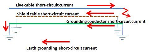
The return current resulted from phase-to-earth-to-phase [double-phase grounding] splits in cable shield, grounding conductor and earth itself. Roughly calculating, neglecting the reactance- if the cable screen is of aluminum foil longitudinally applied, the cross-sectional area of 25 mm^2 the resistance will be Rsh=1/35*1000/25=1.14 ohm/km at 20oC, the grounding conductor of 1*300 mm^2 copper Rgrcnd=1/58*1000/300=0.057 ohm/km and Earth grounding resistance will be Rg1+Rg2+0.05 of minimum 1 ohm[Rg1 and Rg2 grounding resistance of both sites] then Rtotal=1/(1/1.14+1/0.057*1)=0.054 ohm/km
The presumable shield current will be:
Ish=Ic*0.054/1.14 and if Ic=40 kA then Ish=1.8 kA.
In my opinion also if the cable construction is as per EDF NFC-33-226 standard the short-circuit withstand capability has to be around 3.2 kA.

MV_cable_short-circuit_ppqque.jpg
 
Status
Not open for further replies.
Back
Top