Eng-Tips is the largest engineering community on the Internet

Intelligent Work Forums for Engineering Professionals

MV substation auxiliaries T/F (50 kVA) trips when main T/F (3.3 MVA) is energized 1

Status
Not open for further replies.

Oblsss

Electrical
Nov 7, 2013
42
0
0
IL
Dear Sirs,

We have a MV switchboard consisting of three CB's:
1) one connected to the 20 kV grid,
2) the second feeding a 3.3 MVA 3-winding transformer and
3) the third feeding the substation auxiliaries 50 kVA 2-winding transformer.

We are experiencing several nuisance trips of the auxiliaries T/F CB when the main transformer is energized.
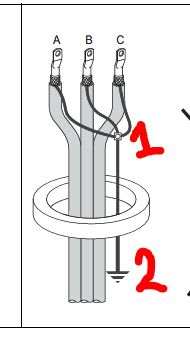
The tripping is Ι0> ground fault which is measured by a core balance current transformer at the cables compartment of the MV switchboard.

What I cannot understand is why I don't have Ι0> ground fault when I am energizing the auxiliaries T/F?
The protection relay used is a Schneider Electric Sepam S10.

Any insight would be greatly appreciated!

George
 
Replies continue below

Recommended for you

The Io> in relay S10 is not operating while the aux transformer is being energised. So, it seems the trip is not really on Io> exceeding the set threshold.
Could it be something to do with voltage dip while energising main transformer.
Some relays are known to close the trip output contacts when their auxiliary voltage dips below a limit.
You may want to checkout!
 
Has it been that way since the gear was first energized or is it a new problem?

I’ll see your silver lining and raise you two black clouds. - Protection Operations
 
Thank you for your answers,

@RRaghunath
Relay auxiliary voltage comes from a different power supply!

@davidbeach
I have 4 similar substations, the problem occurs consistently at 2 of them since day one. (This may relate to the relation between inrush current and external grid impedance?)
For your information, these are electric traction substations with a maximum of 1500 m distance from each other, all supplied from a different MV public utility feeders.

@Kiribanda

Aux. T/F is DY11, 50/51 protection from phase CT's and 50N/51N protection from core balance CT. Please find the SLD below:
[URL unfurl="true"]https://res.cloudinary.com/engineering-com/image/upload/v1659513427/tips/rs_r4vpir.pdf[/url]
 
One problem with core balance CT installations on medium voltage cable is that the shields go through the CT as part of the cable assembly and then don't come back after they're separated at the terminations. They have to come back through the CT and then be bonded to ground. If they only go through once, any current on the shields can cause the trip, even with no current in the phase conductors. Energization of the main transformer could be causing changes in ground potential, resulting in the shield currents.

I’ll see your silver lining and raise you two black clouds. - Protection Operations
 
@davidbeach

The installation was performed as described in your post:

1_iukpmc.jpg


Point one was connected through an insulator to the earthing bar of the cable compartment (no electrical connection), passed through the core balance CT and then terminated at the earthing bar of the cable compartment (point two).

Nevertheless I have seen I0 measuring 0.1 - 0.2 Amps during normal loading of the transformers but I blamed in at the magnetizing current and the low power of the transformer (50 kVA at 20 kV is 1.5 A).
 
Not to beat a dead horse, but have you seen it installed that way or was it just drawn up to be installed that way. Past experience elsewhere suggests that simply having it detailed correctly isn't always enough, unfortunately.

That it's never worked correctly is an important clue; it should have and therefore there's an installation or relay setting issue. The routing of the grounds is undoubtedly not the only possible construction issue.

I don't know what it is, but my guess is that when you do find it you'll wonder how something so obvious could have been overlooked so long. Installation teething problems seem to have a way of turning out like that.

Figure out every difference between the two that work right and the two that don't. Different crews? If so, maybe the crew from one that works right can look at one that doesn't?

Good luck and happy hunting.

I’ll see your silver lining and raise you two black clouds. - Protection Operations
 
It looks like when the aux. transformer is energized from its DELTA side the spill over current (3I0) of in-rush due to CT mismatch
may flow through some spurious grounding path connected to main transformer grounding system. Therefore, after temporary
disconnecting the residual CT connection energize the aux transformer to confirm whether the tripping is still persists.
 
@Kiribanda

Please notice that:

[highlight yellow]We are experiencing several nuisance trips of the auxiliaries T/F CB when the main transformer is energized.[/highlight]

If I disconnect the residual CT connection there will be no tripping because this CT is the input for the 50N/51N protection that trips the breaker.
Please explain me a little more what you are thinking.
 
In your SLD there is NO main transformer. Only two transformer feeders (T1 through Q2 & Taux through Q3).
Pl. indicate the main transformer and its connection symbol on the SLD.
 
@Kiribanda

Main transformer is T1 due to higher power (3.3 MVA) compared to the Aux. T2 (50 kVA).
T1 is a 3 winding Transformer, D0doy11 connected.
 
I will stand with my previous insight. When you energize the main transformer T1, the spill over current (3I0)
generated due to possible CT mismatch, will pass through Point # 2 of the shield earthing of CBCT of Aux Transformer
and trips its 3I0 protection. Because they are in very close proximity.
So you have to temporary disconnect the Point # 2 and isolate it properly from all earthing points, and then
re-energize the main transformer to verify whether 3I0 of Aux. transformer is still working or not.
 
Status
Not open for further replies.
Back
Top