Continue to Site

Eng-Tips is the largest engineering community on the Internet

Intelligent Work Forums for Engineering Professionals

  • Congratulations KootK on being selected by the Eng-Tips community for having the most helpful posts in the forums last week. Way to Go!

my analysis of steel cantilever beam - anchoring

Status
Not open for further replies.

n3jc

Civil/Environmental
Nov 7, 2016
187
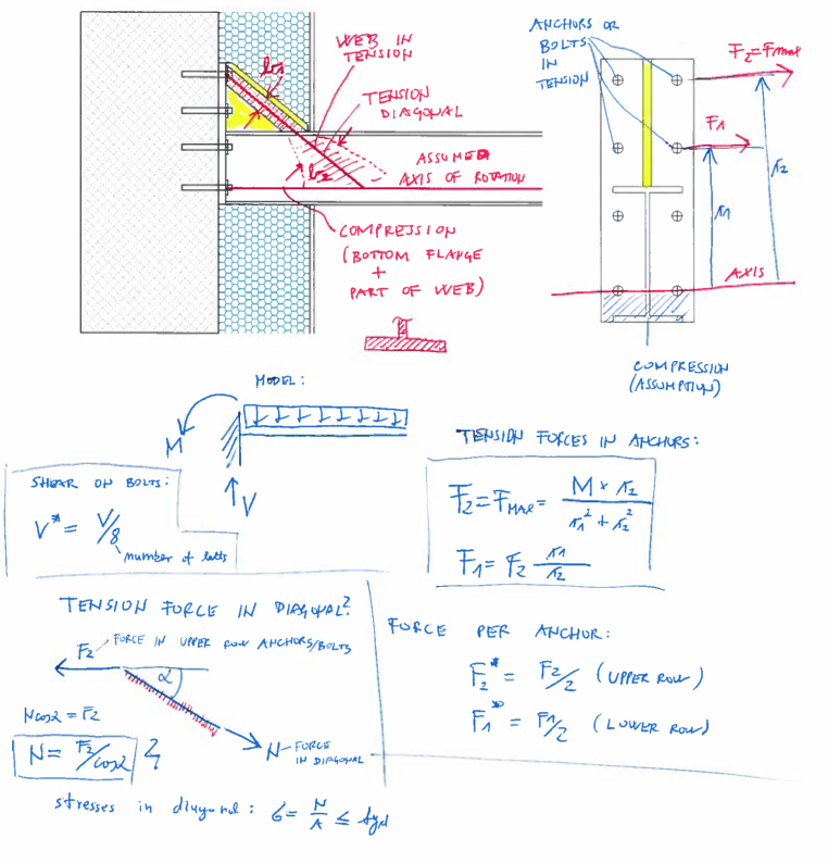
My assumptions:
a) axis of rotation is approx. around the lowest row of anchors
b) only the upper two rows of anchors (total 4) are in tension, the rest are not considered when calculating tension
c) shear force V is equally destributed among anchors

My questions:
1) how do you determine a participating width (b1 in picture) of tension diagonal (in additional vertical steel plate)?
2) how do you control a web of steel beam in tension - again what participating width do you take (b2 in picture)?
3) I calculated tension force in diagonal from force in upper row of anchors as shown bellow - is this OK?
4) I dont know exactly how should I control bottom flange in comppresion?


Id appreciate some comments on my assumptions and answers on my questions.
Tnx in advance.
Bye.


K1_rdesca.png


K0_yynby0.png
 
Replies continue below

Recommended for you

Why would only the top two rows be in tension? Surely all rows are allin tension, the tension being the greatest in the top row.
I would take the point of rotation as level with the bottom flange.
 
1 through 3 are largely engineering judgement IMHO.

#4 is often controlled by bearing on the concrete. It is a quadratic equation, but you can pretty easily solve for the point of rotation making some simple assumptions on the distribution of reactions to the rows of bolts. I would make my life easier and assume the bottom row of bolts take all the shear (if it can), and use the remaining rows to handle the tension. It would behoove you to extend the bearing plate a little below the beam instead of stopping it flush.
 
Its more conservative to consider only top 2 rows to be in tension. Also third row doesnt get much tension.
I dont think its conservative to take axis of rotation aroun bottom flange. In reality there has to be some compression zone in the are of bottom flange in my opinion.

Id really like to hear how do you guys consider participating width of a tension diagonal and beam web.

Id really apreciate if someone can direct me / post some worked examples of stuff like this.

tnx
 
dcarr82775 said:
I would make my life easier and assume the bottom row of bolts take all the shear (if it can), and use the remaining rows to handle the tension.

I think if you're going to make this assumption, then the bolts you're assuming aren't taking shear should at least have slotted holes. Otherwise, they will take some of the shear whether you want them to or not. I've seen other engineers use this assumption before, and I don't agree with it...you can't pick and choose which anchors take shear and which don't, unless you detail the connection appropriately.

It's conservative to only account for tension in the top anchors, and they will take most of the tension anyway...but if you're having a hard time getting anchors to work, then I would account for the actual tension distribution. Have you tried putting the anchor design into PROFIS or similar software? Might be useful as a comparison to your hand calculations if nothing else.

For the width of your diagonal tension - Boldgett covers this for a stiffener in compression (section 5.3, Design of Welded Structures). If you don't have access to this text, let me know and I will describe what he uses.
 
Thank you for your suggestion CANPRO. I completely agree about not able to pick which anchor will take shear and which tension only. Its not logical.
Unfortunately I dont have access to text you suggested. If you find time, Id appreciate if you can describe a method.

regards
 
PROFIS is free software available from HILTI.

Perfectly valid assumption, and yes of course it requires detailing just like every other assumption made in design. It only makes sense to limit shear on the anchors with the most tension.
 
It is assumed you have checked the group effect of those anchor bolts. The short lengths appear very questionable as to suitability, too close together? not deep enough?. Only one beam? spacing and effect on wall?
 
I agree it's a bit illogical using zero shear on top anchors. It's easy enough for the top two anchors to carry all the shear regardless of our how we detail it.

My answers:

1) Twice the bolt-hole-to-web distance. Assumes end plate "Stub Tee" can carry loads back to stiffener.
2) Beam shear design issue. Put in stiffeners if you are worried about diagonal tension/compression. I think if you manage to cripple the web your connection is working ok :)
3) I would use top 4
4) Controlled by bearing surface crushing. It's the same concept as reinforced concrete compression block. As noted you can extend the plate a bit deeper past the beam and get a bigger lever arm.
 
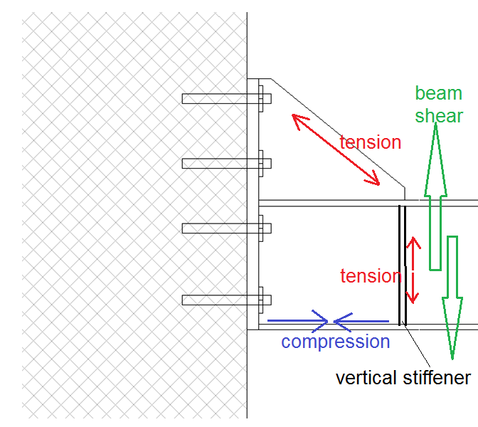
2) By beam shear design issue - you mean in a case I put a vertical stiffener between beam flanges, Im not dealing with a web tension problem anymore since stiffener takes care of this force, but instead I get shear in a beam as a result? something like this?


zz_edofat.png
 
Status
Not open for further replies.

Part and Inventory Search

Sponsor