Continue to Site

Eng-Tips is the largest engineering community on the Internet

Intelligent Work Forums for Engineering Professionals

  • Congratulations IDS on being selected by the Eng-Tips community for having the most helpful posts in the forums last week. Way to Go!

Nastran Composite Modeling

Status
Not open for further replies.

VN1981

Aerospace
Sep 29, 2015
186
Hi,
I am interested in learning on how to model Laminates in Nastran using just Plate elements i.e. without defining the stack up sequence. Can think about it as defining the laminate properties in a smeared way.

Ian Taig provides some guidance but I am unable to comprehend all of it completely. I am posting an excerpt of one such method.

a) Single Anisitropic Panel: For Membrane only panels, the QUAD4 material is specified by a single MAT2 card, the stiffness matrix being calculated using the ADS CF02 program. The fibre angles are specified relative to the 0 deg direction, the orientation of this layer can then be input on the QUAD4 card as either an angle or a Co-ord System.

Nastran QUAD4 element would be specified as:

CQUAD4 1 1 100 101 201 200 17.5

Consider a layup of total thickness 4.0mm :-

Layer Thickness %Thickness (1/2 unit t)
+45 0.5 12.5 .0625
-45 0.5 12.5 .0625
0 2.0 50.0 .25
90 1.0 25.0 .125

CF02 should be run with layer thicknesses totalling UNITY, option 0 giving the stiffness matrix as shown below

PROGRAMME CF02 - ISSUE 2 - ANISITROPIC PLATE STIFFNESS

SYMMETRIC PLANE No Temp or Moisture Used
NO. of Plies = 8 No. of Materials = 1 Angle of 0 deg. Datum = 0.000

Material E1 E2 G12 Nu12 Mat. No.
M 13600 6000 3000 0.3 1

PLY NO. Thickness Angle Material No. Angle with Datum
1 0.0625 45 1 45
2 0.0625 -45 1 -45
3 0.2500 0 1 0
4 0.1250 90 1 90
5 0.1250 90 1 90
6 0.2500 0 1 0
7 0.0625 -45 1 -45
8 0.0625 45 1 45

IN PLANE STIFFNESS MATRIX

0.796633E5 0.974165E4 0.00000E0
0.974165E4 0.470337E5 0.24441E-2
0.00000E0 0.24441E-2 0.10934E5

RIGIDITY MATRIX

0.6535E04 0.1679E4 0.2230E3
0.1679E4 0.2286E4 0.2230E3
0.2230E3 0.2230E3 0.1779E4

The MAT2 material data is specified using the upper triangular terms of the stiffness matrix:

F1 F2 F3 F4 F5 F6 F7 F8
MAT2 1 79663.3 9741.66 0.0 47033.8 0.0 10934.5

The PSHELL card would thus be:

PSHELL PID 1 4.0

My questions in the above process are as follows:

1. Where can I find this CF02 program? Did a quick Google and nothing came up. Is the program included in Nastran?
2. What is (1/2 unit t)? Highlighted in bold
3. Any updated procedure on modeling Laminates as single plates using Nastran?

I can post more information if needed.

Edit: I had formatted the data to appear neatly as columns & rows in a text editor but the forum software has destroyed it and I dunno how to rectify the same. Sorry...
 
Replies continue below

Recommended for you

1. You can use any classical lamination theory software to generate the [A] matrix (in-plane stiffness matrix). eLaminate is a free one on my website and another popular one is the Laminator.
2. That is just half of the layup. It is symmetric (hence the 8 as the number of total plies).
3. If all you care about is the in-plane properties, then you just need to determine the "effective in-plane properties" of the laminate (Ex, Ey, Gxy, nu_xy, nu_yx). The lamination software can provide this. You can then assign these properties to an orthotropic material in the FEM (assuming the laminate is symmetric and balanced). If you just care about the bending properties, you can determine the effective bending moduli and assign those to the FEM. But you can't simultaneously do both with just an orthotropic material (at least not in general).

Brian
 
ESPComposites,
Thanks for the response. So the In-Plane & Rigidity Matricies are nothing but [A] & [D]. Duh!...

So here is the continuation from Ian Taig's notes

If Bending effects are to be modelled, CF02 is used with the full laminate specification in order to obtain a Rigidity (bending) matrix for a UNIT thickness of laminate. The Rigidity matrix is then multiplied by 12.0 and a separate MAT2 card specified for the bending material. A typical stacking sequence is shown below together with CF02 output.

PLY NO. THK Angle Mat. No. Angle with Datum
1 0.0625 0.0 1 0
2 0.0625 45.0 1 45.0
3 0.0625 0.0 1 0.0
4 0.0625 -45.0 1 -45.0
5 0.0625 0 1 0
6 0.0625 90.0 1 90.0
7 0.0625 0.0 1 0.0
8 0.0625 90.0 1 90.0
9 0.0625 90.0 1 90.0
10 0.0625 0.0 1 0.0
11 0.0625 90.0 1 90.0
12 0.0625 0.0 1 0.0
13 0.0625 -45.0 1 -45.0
14 0.0625 0.0 1 0.0
15 0.0625 45.0 1 45.0
16 0.0625 0.0 1 0.0

INPLANE STIFFNESS MATRIX

0.7966E5 0.9741E4 0.0000E0
0.9741E4 0.4703E5 0.2441E-2
0.0000E0 0.2441E-2 0.1093E5

Rigidity Matrix

0.7986E4 0.1121E4 0.3505E3
0.1121E4 0.1952E4 0.3505E3
0.3505E3 0.3505E3 0.1221E4

As can be seen the Rigidity matrix is quite different for the fully specified layup, and if bending effects are critical, for buckling etc., the exact stacking sequence should be used.

Multiplying the matrix by 12.0 gives an equivalent material for bending effects, the full thickness being used. THe ratio 12I/T^3 should be set to 1.0 on the PSHELL card.

The Bending MAT2 card would be:

MAT2 2 95827.7 13461.0 4206.1 23430.8 4206.1 14653.8

and the PSHELL would now be

PSHELL PID 1 4.0 2 1.0

If the MID3 field is blank the Transverse Shear flexibility is zero (Infinitely stiff). Normally this should be specified and for CFC laminates the matrix (glue) material should be used with E=6000 say, and an effective thickness of between 0.4 & 1.0

The final PSHELL card would be:

PSHELL PID 1 4.0 2 1.0 3 0.8

where the Transverse shear material is given on the MAT1 card:

MAT1 3 6000.0 0.3

Does the above mean that both in-plane & bending effects can be captured using one PSHELL card?

I guess one of the limitations of the above method is that stack up sequence has to be symmetric since there is no provision to input axial-bending coupling (b) matrix values.

I will have to try the above method for simple test cases and verify it.

I have another question, not related to the above, but did not want to start a new thread. One of the design guidelines provided in Niu includes the following

Beam subjected to Bending, shear & end loading:
1. Include 0 deg plies in caps to efficiently sustain bending induced axial loads.
2. Include +- 45 deg plies in web to sustain shear and in Caps to stabilize flanges

Question: What exactly does the plus/minus 45 deg plies in caps stabilize against? I was told that +-45 deg plies stabilize the 0 deg plies from splitting. Is this accurate?


- Yes, you can create an "effective thickness" that is not equal to the actual thickness. This will allow the flexural rigidity to be equal.

- Regarding your second question, have a look at the elastic stability for a laminate loaded in compression (1 edge is free and the 3 other edges are supported in some manner). The D66 term (twisting stiffness) tends to dominate the capability. The +/-45 plies tend to drive the D66 value. So you need some +/-45 plies to ensure the elastic stability is not unreasonably low. Of course, other design rules usually, but not always ensure this does not happen (consideration for fastened joints, fastened repairs, minimize interlaminar stresses via homogenization, etc.).

Brian
 
ESPComposites,
Sorry to be a noob but can you please elaborate on the effective thickness you have mentioned. Also why are they multiplying the Rigidity Matrix with factor 12.0? Since I can get values of [A] & [D] using in-built function in Nastran, I can use actual thickness (plies/laminate) instead of UNIT thickness as suggested by Ian Taig.

Secondly, how do I check for elastic stability of a laminate?

Thx a lot.
 
Here are the basic principles and you can apply however you like.

- If you use the actual ply properties and stacking sequence in NASTRAN (with PCOMP), then you don't need to do anything else (provided you don't care about transverse shear deformation). You are done. NASTRAN will use laminated plate theory to internally calculate the [A] and [D] matrices.

- If you want to use a "smeared" approach, then you calculate the [A] and [D] matrices with any laminated plate program. The smeared approach I am referring to is to use a shell element with an orthotropic material (not specific to any FE code). If you ONLY care about the in-plane response, you can calculate the effective in-plane laminate properties Ex, Ey, Gxy, nu_xy, nu_yz from the [A] matrix (laminate program does this). You can then input those, with actual thickness.

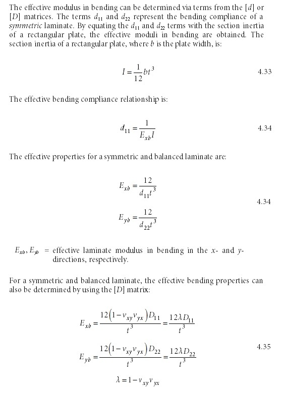
Lets say you ONLY want to simulate the flexural properties, such as for plate stability without the effects of transverse shear. You have a couple options. You can use the actual thickness with the effective bending moduli. The approach is to equate the EI of the laminate (from [D]) to the EI of a solid material. This is done by recognizing that the 2nd moment of inertia of a rectangle is (1/12)bt^3 (See below). You could also use a unit thickness with a corresponding Ex and Ey. For the torsional rigidity of a solid open section, GJ = G(1/3)bt^3 and for the laminate it is 4b/d66 so it works out with the same multiplier of 12. Be careful about using either the stiffness [D] matrix or the compliance [d] matrix. See attached image.

*See note below if you want to use a PSHELL to simultaneously incorporate the [A], , [D] matrices including the effect of transverse shear deformation. Transverse shear deformations are important for thicker laminates or sandwiches. The matrix will be nonzero if the laminate is not symmetric.

- Just apply the plate stability equation for laminates. There are a lot of resources, but a free one that I think has it is MIL-HDBK-17.

effective_bending_props_byvakv.jpg


P.S. I was informed that you can capture the full effects of the [A], , [D] matrices + transverse shear deformation with the PSHELL. This approach may also be considered.

pshell_ztm0kh.jpg
 
"Does the above mean that both in-plane & bending effects can be captured using one PSHELL card? "

> Yes, both can be included via two MAT2 cards (MID1, MID2) referenced on the PSHELL card. The third MAT2 card (MID3) can contain the transverse shear stiffness values, and the fourth MAT2 card (MID4) can contain the bending-extensional coupling .
 
Folks,
Thanks a lot for your latest posts. Will try the procedures out...
 
Just to clarify a couple points:

- If you only want to capture the axial or flexural properties, you can do so with effective moduli and a single MAT8 (which can also capture transverse shear). These moduli (and effective Poisson terms) are more directly obtained via the [a] or [d] matrices or less directly via the [A] or [D] matrices + Poisson terms. I like this approach for simple problems that don't require coupling because the material properties are intuitive (modulus of elasticity, shear modulus, Poisson's ratio) and it is easily implemented in various FE programs. It helps if your laminate program calculates the effective properties for you. Examples of use are to determine in-plane stress concentrations or elastic stability of symmetric laminates.

- As SWComposites stated, the use of PSHELL + 4 MAT2 cards is the most flexible approach because the in-plane/bending coupling can be captured. However, this approach may not exist for all FE programs. Note that the MAT2 inputs are not actually material properties, but are plate properties (MSC calls this the "material property matrix"). This is the reason the [A] and [D] matrices are the base inputs (as opposed to being based directly on the [a] or [d] properties).

Brian
 
Hi,
I was trying to learn & verify PSHELL smear procedure (based on the above posted information) in FE (Nastran) earlier this morning. The test case I have contains one component which is of Graphite/Epoxy Fabric. The referenced (test) case doesn't specify the trade name or specifics of which Gr/Ep Fabric the component is!

I am trying to obtain Mech Properties for the above material so that I can feed it in to Nastran MAT8 card. I looked in MIL-HDBK-17 and I was able to obtain most properties expect for Poisson's Ratio. I even checked on Hexcel product sheets but it does not specify Poisson's Ratio.

Anyways, I left Poisson's Ratio number as blank in the software and created the stack up sequence and asked the software to compute equivalent Ex, Ey etc. properties. The value of longitudinal in-plane Young's Modulus (Ex) as obtained from software is twice as what is given in my referenced case. Upon further inspection, I found out that in the reference case, Carpet Plot of Gr/Epoxy Tape was used and Ex was obtained.

I have a couple of questions regarding the above.
1. Is it acceptable to use Gr/Epoxy Tape Mech Properties for Fabric style as well?
2. Outside of proprietary information & CMH-17, any other sources apart from Hdbk-17 which contains comprehensive collection of composite properties?
3. This kinda of follows Q1 & Q2. Any recommendations on how to accurately input MAT 8 entry for Fabric styles? Any titbits or pointers which come out of experience would be helpful.

Thanks in advance,
- VN

Edit: Whole section cleaned up & questions paraphrased for better coherence. I hope the above makes sense.
 
Hey ESPComposites,
Thanks for the insights in to D66's term contribution to elastic stability of laminate. I did some simple calc on Uniaxial Compressive load with different edge supports for various laminate stacking sequences and it was illuminating to see how pronounced the effect of D66 term is on critical force.
 
Poisson's is in MIL-HDBK-17 (now known as CMH-17). E.g., vol. 2, §4.2.9. See also the NIAR/NCAMP material data at Wichita. has a lot of materials.

As is usual for woven carbon, nu1212) is about 0.05.

If it's not there for the exact material that you have, just use a couple of values (say 0.02 and 0.06) and see how much difference it makes. Any 50–70% fiber volume fraction woven carbon/polymer will be between 0.04 and 0.06.

The CF02 program you ask about is a laminate analysis program. If you do not have one, you could try Brian Esp's version at .

MAT8s need the usual orthotropic variables. The out-of-plane shear moduli can be approximated by the in-plane shear modulus, or if you have it, the in-plane shear modulus for a unidirectional version of your material.

D66 is the torsional stiffness of the laminate and has such a pronounced effect on buckling that putting the 45° plies on the outside usually increases buckling load in spite of the reduction in bending stiffness (D11 and D22) that doing this also causes. I have often wondered where the buckled laminate shape is in torsion and apart from being a bit baffled I can only think it must be towards the corners of a rectangular plate. If anyone could elaborate on this I'd be grateful!
 
So, as expected, I am having issues with replicating smeared laminate procedure in NASTRAN. The test case I have is a Gr/EP Wet Laminate subjected to uniaxial Tensile load. The geometry is a simple rectangular plate of dimensions 5" (L) x 5" (W) x 0.22925" (t). The laminate config is 6 plies of 0 degrees & 1 ply of 90 degree. Each ply thickness is 0.03275". The loading is 2000 lbs/in.

I followed instructions provided in the AERSYS-7001 document for which the link was provided earlier, to compute MID1,2 & 4 matrices. I am posting the values below

[A] =

[4.04E6 8.31E4 -2.2E-3
8.31E4 9.02E5 -2.5E-2
-2.2E-3 -2.5E-2 2.75E5]

=

[-6.1E4 0.00E0 -2.2E-4
0.00E0 6.17E4 -2.4E-3
-2.2E5 -2.4E-3 -4.8E-4]

[D] =

[1.73E4 3.64E2 -2.1E-5
3.64E2 7.32E3 -2.4E-4
-2.1E-5 -2.4E-4 +1.2E3]

t = 0.22925"
t^2 = 0.05255
t^3 = 0.01204

MID1 = [A]/t
MID2 = [D]*(12/t^3)
MID3 = (B)*(-1/t^2)

MID1 = [ 17622682.66 36.24E4 -9.6E-3
36.27E4 39.34E5 -10.90E-2
-9.6E-3 -10.90E-2 +12E5]

MID2 = [ 1.72e7 3.63e5 -2.09e-2
3.63E5 7.29E6 -2.39E1
-2.09E-2 -2.39E1 +1.20E6]

MID4 = [ +116.08E4 0.00 +41.86E-4
+0.0 -117.41E4 +45.67E-3
+41.86E-4 +45.67E-3 +91.35E-4]


Here is the some contents of the BDF file

PSHELL 1 1 .22925 2 1.
3
$ Referenced Material Records
$ Material Record : MID1
$ Description of Material : Date: 15-Dec-15 Time: 10:05:06
$ Membrane material properties
MAT2* 1 1.76227+7 362400. -.0096
* 3.934+6 -.109 1.2+6 .055
$ Material Record : MID4
$ Description of Material : Date: 15-Dec-15 Time: 10:05:06
$ Coupling material properties
MAT2* 3 1.1608+6 0. .004186
* -1.1741+6 .04567 .009135 .055
$ Material Record : MID2
$ Description of Material : Date: 15-Dec-15 Time: 10:05:06
$ Bending material properties
MAT2* 2 1.4368+6 30232. -.0017441
* 600500. -.019935 102160. .055

The expected axial stress is 64,400 psi. But I am getting a peak stress of 8950 psi.

Also, I was getting 9050 error. "USER FATAL MESSAGE 9050 (SUBDMAP SEKRRS). RUN TERMINATED DUE TO EXCESSIVE PIVOT RATIOS IN MATRIX KLL". Had to use PARAM, BAILOUT, -1 to proceed. The nodes on which load was applied were experiencing out-of-plane translation & rotations (per BDF file).

I would appreciate experienced folks to debug my bdf file is possible and let me know where I could have gone wrong.

One issue I am unable to understand from Ian Taig's notes is on how to specify angle in CQUAD entry.

CQUAD4 1 1 100 101 201 200 17.5

Is the angle value in the above CQUAD entry means any "base" angle of a certain ply?

RB1957, thanks for the source. I will look it up.
 
Folks,
I would highly appreciate if some could help me debug the above problem and resolve the issue. It would be nice for me to have knowledge of modeling of Composite Laminates using smear (PSHELL) approach.

Thx in advance,
- V

 
Status
Not open for further replies.

Part and Inventory Search

Sponsor