Continue to Site

Eng-Tips is the largest engineering community on the Internet

Intelligent Work Forums for Engineering Professionals

  • Congratulations KootK on being selected by the Eng-Tips community for having the most helpful posts in the forums last week. Way to Go!

Natural Freq of Tapered Pole with Lumped Mass 4

Status
Not open for further replies.

ReverenceEng

Structural
Feb 18, 2016
81
Greetings!

Have a ~200 FT pole Sign with a huge cabinet on top. As such, we have a lumped mass at the top, and we have what I would assume to be a non-negligible mass of the pipe along its length, which decreases along the length from top to bottom. Obviously, 'I' decreases, too.

There is a related post from about a decade ago, which gives some insight, but it seems the responses and some of the resources such as ASCE commentary are limited to cases with a lumped mass or a pipe with a relatively uniform mass and 'I' but no ass at the top.

Is there a good approximation (such as a summation) for working with a multi-stage pipe structure ("tapered" pipe) and with a lumped mass that can be done by hand without jumping into the depths of modal analysis in RISA (or the like)?

Maybe there is a resource out there I have overlooked?

Asking for a friend.
 
Replies continue below

Recommended for you

One suggestion- see Section 15.4.4 in ASCE 7-16. For that application, I would approximate the tapered shaft as a number of beam segments with stiffness and mass of segments varying as you go up. This is not a "hand" calculation, but is not too tedious if done by Excel.
 
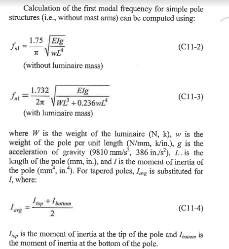
In the AASHTO standard sign spec (Standard Specification for Structural Supports for Highway Signs, Luminaires, and Traffic Signals, 5th Edition) Equation C11.3 gives an approximation of the natural frequency of a tapered pole with a concentrated mass at the top. I recently compared the results to the observed oscillation of a 120' high mast light light tower, and the calculated frequency was within 10% of the observed.

Rod Smith, P.E., The artist formerly known as HotRod10
 
Can also make a program (mathcad) that solves the integral with M(x) and I(x) to get the flexibility of the shaft.
 
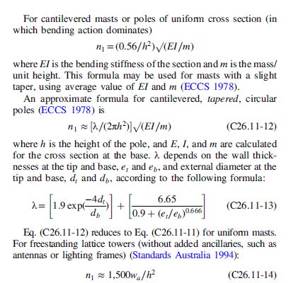
Refer to ASCE 7-16 C26.11 page 753

Natural_freq._tapered_pole_ounqlh.jpg
 
Here's the Equation out of AASHTO:

Capture_db9dmy.png


Rod Smith, P.E., The artist formerly known as HotRod10
 
Rayleigh's method will give you the first (lowest) natural frequency with ease. Another option is to code a small FEA solver in e.g., python or Mathematica; you don't need to use lumped mass in that case, just take density and 2nd moment of area of the pole at each segment as an input from an excel file. The third option is the canned solution proposed by BridgeSmith.

To be honest, a natural frequency (eigenvalue problem) analysis with FEA software is the most accurate way to solve this method, and all hand methods (except for a cantilever beam eigenvalue problem solver coded by yourself) boil down to rough approximations of what FEA will provide you.

Don't listen to the engineers who claim that FEA should be avoided and that hand-calculations are always required - it should not and they are not. In fact, making hand-calculations is just an error-prone way to achieve the same thing as FEA software. Assuming that you understand the FEA theory (e.g., static analysis, non-linear (geometry/material/boundary conditions) analysis, linearized buckling and eigenfrequency analysis, and maybe some dynamic analysis (time integration is the only new thing here)) and have a solid grasp of how to provide realistic boundary conditions, the FEA software is unbeatable in accuracy and time-efficiency. If you do not understand FEA and want to do structural analysis and design, I recommend to enroll in a course or two at university to master the basics.
 
To be honest, a natural frequency (eigenvalue problem) analysis with FEA software is the most accurate way to solve this method, and all hand methods (except for a cantilever beam eigenvalue problem solver coded by yourself) boil down to rough approximations of what FEA will provide you.
I agree with that. The question then becomes, how accurate does your solution need to be? Especially with a multi-section pole with slip joints, even the FEA isn't going to get you a really accurate value unless you could somehow model all the imperfections and gaps at the overlap, and also the stiffness of the foundation.

We're in the midst of a redesign of our 80' high mast light poles, and we've had an FEA done, an incremental Excel calculation, and the simplified method I posted earlier. The Excel solution and the FEA are within 1% of each other, and simplified solution was within 5% of both. The design of the tuned mass damper will still be refined using full-scale testing, because the FEA is not expected to be accurate enough to predict the configuration of the damper that will be needed, according to our consultant that specializes in this type of work. We'll find out what the actual natural frequency of the system is when they're finished.

Rod Smith, P.E., The artist formerly known as HotRod10
 
centondollar said:
Rayleigh's method will give you the first (lowest) natural frequency with ease

The method JStephen pointed towards in ASCE is essentially the Rayleigh method.

I'd say there is another easy way to do this.
1) Calculate the mass of the "huge cabinet".
2) Model the tapered column in RISA, or SAP or whatever program you use.
3) Apply the vertical load from the column and cabinet on the model, and apply a 1 kip lateral force (more if you need more significant figures). See what kind of reaction you get at the base. This gives you the stiffness (Kips per inch of deflection). If you had P-Delta included in your analysis then this also accounts for the loss of stiffness due to 2nd order effects.

4) Finally, the natural period of the structure would be: T = 2*pi * sqrt(M/K). And, frequency = 1/T.
 
Hey Josh - Any thoughts on using the 'Dynamics' solution in Risa for determining frequency/period?
 
I just now had the realization that I don't know why the natural frequency is needed here. I've never used it to calculate the loading or reactions for the design of a pole. I didn't need the frequency until I got involved in the design of the damper system.

Rod Smith, P.E., The artist formerly known as HotRod10
 
If he's using ASCE - frequency/period is needed for gust effect factor calculation. I believe in the past you've mentioned AASHTO says it's conservative and acceptable to use 1.15 for high mast light poles.
 
azcats said:
Hey Josh - Any thoughts on using the 'Dynamics' solution in Risa for determining frequency/period?

Yeah, that should be fine. I think the OP was looking for a way to validate the type of results he'd get from that kind of analysis.

The only "issue" with a RISA frequency calculation is that it won't account for the 2nd order effect. Meaning it will be a bit stiffer than reality because of the P-Delta softening of the lateral stiffness.

The method I suggested (for hand calc) would allow you to validate RISA's number and compare it to what you'd get if P-Delta were included.

Caveat:
I worked for RISA for 16 years. But, that ended in 2017 (under some less than amiable circumstances). So, my knowledge of RISA may not reflect changes made recently. Also, I now work for one of RISA's competitors (CSI / SAP), so I have some bias against RISA and cannot be considered a neutral observer.
 
If he's using ASCE - frequency/period is needed for gust effect factor calculation.

Ah, I didn't know that.

I believe in the past you've mentioned AASHTO says it's conservative and acceptable to use 1.15 for high mast light poles.

I don't remember for sure. For general design, the gust factor was 1.3 in previous versions of the spec, but the LRFD now directly calculates the pressure from the gust wind speed. For high mast poles, and for most other poles, sign structures, etc. the design wind speed is something we give a quick check after we size it to meet the fatigue stress limits. The design ratios (for the 100 or 115 mph wind speed) for most of our poles are below 0.5, so once we get them beefy enough to pass the fatigue checks, we could check them for a 130 or 140 mph wind speed and they'd still pass.

Rod Smith, P.E., The artist formerly known as HotRod10
 
azcats said:
I believe in the past you've mentioned AASHTO says it's conservative and acceptable to use 1.15 for high mast light poles.

I mis-remembered this and confused you w/ someone else Rod. It's a minimum of 1.14 and was referenced here:
No idea if that's still current as I'm not an AASHTO user...
 
Thanks for the answers, everyone!

And yes, we are designing to ASCE 7 for an architectural pole sign (for a bank) that is technically not subject to AASHTO standards, but in reality, I should have thought about that since we do design structures to AASHTO using the LRFDLTS-1 from time to time. So thank you!

To answer the recent questions, the pole sign is 183' tall and yes, we are trying to get a more accurate Gust factor since this is abnormally high.

Our initial estimation was a period of 2.5 sec (0.4 Hz) for initial calculations and it seems the method from AASHTO puts us at 0.56. Interestingly, we started at 1.15 as our general standard for higher signs, but it was causing this to be a bit impractical, so we needed to see if we could reasonably refine things.

And also yes, I am looking for a good starting and comparison point before we dive into the FEM. There are a lot of "buttons" and settings in RISA and other software (a lot of opportunities for an easy wrong click), so we believe it's important to understand where these numbers are coming from and to reasonably be able to verify findings).

I am going to dive back into AASHTO since it has been a minute and look into general deflection limits to see if they have guidance there.


Status
Not open for further replies.

Part and Inventory Search

Sponsor