Continue to Site

Eng-Tips is the largest engineering community on the Internet

Intelligent Work Forums for Engineering Professionals

  • Congratulations GregLocock on being selected by the Eng-Tips community for having the most helpful posts in the forums last week. Way to Go!

Natural Gas Pipe Sizing: Velocity vs Pressure Drop

Status
Not open for further replies.

michael333

Mechanical
Jun 15, 2007
20
Hello Out There,

Context:
I'm sizing a natural gas(NG) line (high pressure) from an a tie-in to an existing 6"main gas line over to 4 new gas-fired generators. First time in sizing a high pressure piping section branch.
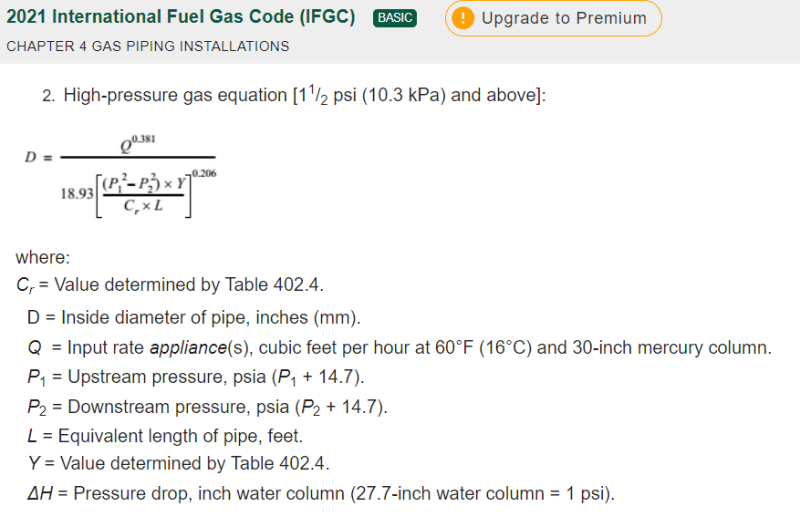
I'm using the high-pressure gas equation 4-2 from the IFGC. It's been working well for other parts of the system.
I'm deciding between a new 3 inch or 4 inch for this particular piping section branch? My understanding is pay attention to velocity vs pressure drop in sizing high pressure NG piping.

With the above said, here are the parameters:
Have 65 psig available at the beginning tie-in point(node) at the existing 6"main as my starting point for the piping section branch.
402 FT total equivalent length for the piping section branch to the next node,
4": I have a 1.5 psig drop in the piping section branch
3": Have a 5.65 psig drop in the piping section branch,
0.60 SG, 60.0 deg F

My question:
I calculated the gas velocity, based on an equation I googled for gas line sizing. But I'm not sure about my answer due to units in the equation for pipe ID. Inches vs FT.
For the 3" pipe section, I came up with approximately 104 fps vs 250 fps pending if I use inches or FT for the piping diameter in the equation.
Does anyone know which velocity is correct for a 3" Sch 40 steel pipe at the above parameters?
Any advice on which line size to go with: 3" vs 4"?

Thank You,
Michael
 
Replies continue below

Recommended for you

"It's been working well for other parts of the system" but you don't know what units to use??

IFGC eq. 4-2 calls for pipe ID in inches. You also need the required flow rate and minimum delivery pressure to the generators to confirm whether the pipe sizes you propose might work.

Capture_t0jrha.png
 
I'd go for considerably less velocity, around 60 fps. Not over 100 fps if at all possible.
For short lines as you have, pressure drop usually is not the problem. It's noise.
I'd probably go with a 4.5" OD. That should work. 6" is probably too large, but for a short bit of pipe, not totally off the wall. Why? Consider the potential of adding 4 more units in the future. Gen stations always seem to grow demand much faster than expected.

You might consider using the Colebrook-White equation. Or others, some that do not require iteration. They accept variables that you can control and change as needed to suit a wide variety of conditions and gives answers without the use of tables in which you have no idea as to how they were derived.
Even with iteration, CW can be calculated in 3 or 4 tries.
Colebrook-White explained here. A PDF.

My personal noniterative solution favorite is Churchill

Einstein gave the same test to students every year. When asked why he would do something like that, "Because the answers had changed."
 
It's always a bit surprising what different people think is high pressure.... 65 psi is fairly low to me.

But at 400ft length, pressure drop should be very small. Less than 2 psi.

3 inch looks too small and you need 4. It's this steel or PE?

Remember - More details = better answers
Also: If you get a response it's polite to respond to it.
 
What is the flowrate? My calculations indicate that it takes about 24.3 CFS flow in 4" sch. 40 to produce 1.5 psi pressure drop at your given conditions using Darcy Gas equation with resulting velocity 51.2 FPS. This seems reasonable design.

I meant to say 24.3 SCFS (at 14.7 psia)
 
And a very good velocity.

Einstein gave the same test to students every year. When asked why he would do something like that, "Because the answers had changed."
 
What is gas fired generator - at 65psig, you probably mean gas engine.
In my experience, there is another criterion to be considered also in setting up supply FG lines to gas turbine or gas engine generators when more than 1 machine is running. If one machines trips, the buffer volume held up in the upstream supply line plus any inline buffer vessels should provide sufficient response time to the upstream pressure controller so that it can react to close the PCV in time to prevent a high pressure trip of the remaining machines still online. See if this applies to your system and increase supply pipe size or buffer vessel volume to suit.
 
You can also consider the portion of the cost increment burred 3 inch pipe and 6 inch pipe will mostly be the cost of job mobilization and excavation.

For reasons cited above I would tend to oversize this pipe.

At 60 psi PE pipe is a reasonable material choice for the underground portion of the piping.
 
My 2 cents, although I have not sized natural gas pipes:
-noise should not be an issue for mach numbers below 0.15, and the discussed velocities are below this value
-a "high pressure" interstate gas pipeline may be operating at 500-1300 psig, and the 65 psig pressure listed above is not really "high pressure", but is above a 60 psig limit sometimes listed by some codes.
-There may be times when the source pressure may swing below 65 psig, so the sizing of the pipe should consider the worst case of lowest upstream pressure

"...when logic, and proportion, have fallen, sloppy dead..." Grace Slick
 
You need to check the generator manufacturer's installation manual.

Story - I once sized piping for a natural gas generator; no pressure drop or noise issues. During commissioning, the generator kept stalling out. Manufacturers rep came out and said it was because I didn't have enough of a "pressure reservoir" at the inlet. I guess the listed flow rate was an average, and the start up flow rate was quite a bit higher. He said I needed to replace the tie ins (3" riser) with a 6" header. I pulled up their installation manual, and sure enough - it was drawn that way - riser increases to an oversized header at the applicance connection. This was a well known generator manufacturer. Not sure if it has changed as it is has been 8 years ago or so.

Point being, if the generator operates at a low pressure (probably a few inches of water column) you need to be careful at the very end/aka after you reduce to delivery pressure.

I do check the installation manuals now.
 
Status
Not open for further replies.

Part and Inventory Search

Sponsor