Eng-Tips is the largest engineering community on the Internet

Intelligent Work Forums for Engineering Professionals

NBCC 2020 - Canopy Wind Load

Status
Not open for further replies.

canstruct12

Structural
Dec 18, 2018
26
0
0
US
Hello Canadian Engineers, I am designing a covered breezeway (roof and 4' high plywood barrier) adjacent to an existing building, there is no gap between the breezeway and the building. As well they are similar heights, as the breezeway roof will be ~2" lower than the building roof and sloped 2% to shed water.

X-Section_hulv5r.png


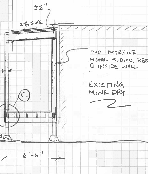
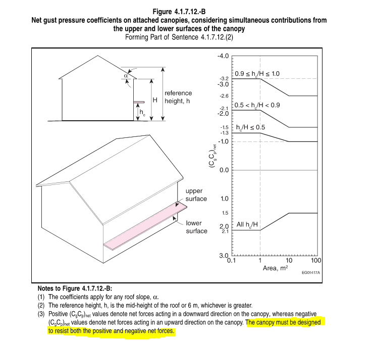
I am using "NBCC 2020 CL 4.1.7.12 - Attached Canopies on Low Buildings with a Height H ≤ 20 m" as this is the most applicable reference I was able to find in the NBCC, as the roof slope does not exceed 2% and there will be no gap between the breezeway and the building.

4.1.7.12_-_1_h7qe5c.png

4.1.7.12_-_2_ut0qz6.png

4.1.7.12_-_3_ooevxk.png


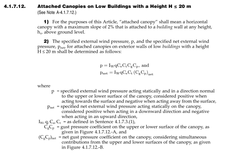
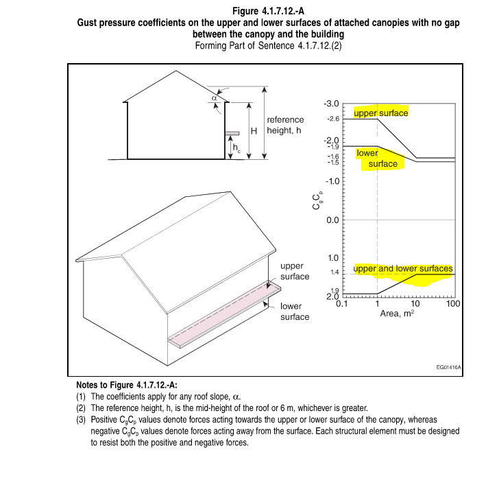
I am uncertain how to apply the loads for CpCg values provided in Figure 4.1.7.12 A.

Figure 4.1.7.12 A shows that there will be forces acting upward and downward, on both the upper and lower surfaces. I am wondering if this is intended to be 4 separate load cases, i.e.

(1)Upward Force on Upper Surface
(2)Downward Force on Upper Surface
(3)Upward Force on Lower Surface
(4)Downward Force on Lower Surface

Any guidance or explanation would be helpful.
 
Replies continue below

Recommended for you

I'm pretty sure that is a net CpCg, not acting on the lower or upper surface. You need to design for uplift and wind pushing the canopy down, as separate load cases.
 
For your situation though, I see this more as an overhang to the roof rather than a canopy, therefore I'd be more partial to be designing it for the C&C loading noted in figure 4.1.7.6.-C for the OC/OS/OR loading noted there.

I don't know if that improves your situation, but it does remove the downward load. The canopy loading gets the downward component from wind hitting the wall above the canopy, you have no wall above the canopy to direct the wind downwards.
 
@jayrod12,thanks for the response, the rational of the wind hitting the wall above the canopy putting downward force on the canopy makes sense and is a good explanation. I was also considering using the C&C diagram in Figure 4.1.7.6.-C, but opted for Figure 4.1.7.12 A&B instead for 2 reasons:

1) Structure is 6'-6" wide, which seems excessive to try to justify as a roof over hang.
2) Structure is independent of the main building structure and planning to use crib footings, so I will be assessing overall resistance to overturning, the C&C does not seem applicable for this.
 
I feel the canopy provisions you wanted to use wouldn't be applicable for overall stability either. That would be considered a component, not a full structure analysis. If you wanted to design that way, I'd likely be using 4.1.7.6-A witha Cpi = +/- 0.7 as per 4.1.7.7. At least for overall structure stability. But I really feel this is more a component than a structure. You're tying in the roof membrane so if it were me I'd likely be designing the entire thing for the OC wind values in 4.1.7.6.-C and just be done with it. At that small, the loads really can't be causing you tons of grief. C&C loads are higher than full building, but not overly penalizing so on something this small.

For 4.1.7.6-A with fully open Cpi values I get a combined CpCg = 3.4 in the upwards direction.

If you use 4.1.7.6.-C, with an area of 4m^2 (assuming this thing is at least as deep into the page as it is wide), the CpCg for oc is in that same range of 3.4. So I don't imagine appreciable difference is structure sizing regardless of the procedure you use.
 
Status
Not open for further replies.
Back
Top