Hi,
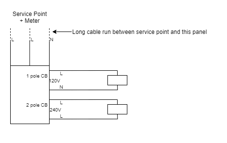
It's not clear to me from the NEC's definition how voltage drop should be calculated in this case (see diagram).
I can find the drop across the cables serving the 2 loads (branch circuits) using the usual 2*I*R formula for each circuit and dividing by 120 for the first load and by 240 for the second. The sum of both drops should be less than 3%. My problem is when I get to calculating the voltage drop (since it is a long run from the service point to the panel board) across the 3 cables. Should I calculate 3*I*R (and assume I to be the sum of both load currents) and divide that by 240? Or calculate 3*I*R (and assume I to be the sum of both load currents) and divide that by 120? Or is the correct formula different? In the end, the drop due to the cables supplying the loads and the cables supplying the panel should be less than 5%.
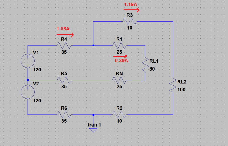
EDIT: I ran a quick LTSPICE simulation to get a feel for it, and it seems that to get the voltage drops I need to calculate:
R*(240load current) + R*(120load current) + R*(240load + 120load currents). This will give me the voltage drops for the cables serving the panel, but then, should I divide this sum over 120 or 240 to be consistent with what the NEC requires?


Thanks for your help,
Luis
It's not clear to me from the NEC's definition how voltage drop should be calculated in this case (see diagram).
I can find the drop across the cables serving the 2 loads (branch circuits) using the usual 2*I*R formula for each circuit and dividing by 120 for the first load and by 240 for the second. The sum of both drops should be less than 3%. My problem is when I get to calculating the voltage drop (since it is a long run from the service point to the panel board) across the 3 cables. Should I calculate 3*I*R (and assume I to be the sum of both load currents) and divide that by 240? Or calculate 3*I*R (and assume I to be the sum of both load currents) and divide that by 120? Or is the correct formula different? In the end, the drop due to the cables supplying the loads and the cables supplying the panel should be less than 5%.
EDIT: I ran a quick LTSPICE simulation to get a feel for it, and it seems that to get the voltage drops I need to calculate:
R*(240load current) + R*(120load current) + R*(240load + 120load currents). This will give me the voltage drops for the cables serving the panel, but then, should I divide this sum over 120 or 240 to be consistent with what the NEC requires?


Thanks for your help,
Luis
