Eng-Tips is the largest engineering community on the Internet

Intelligent Work Forums for Engineering Professionals

NEC Voltage Drop

Status
Not open for further replies.

P1ENG

Structural
Aug 25, 2010
237
0
16
US
I am a structural engineer tasked with finding the maximum wire run length for a simple modular building. The panel has 120v receps with the branch load rating of 900 Watts. So, I'm working with 7.5 amps. I am allowed 2% voltage drop on the branch circuit (ASHRAE requirement I believe). Googling has allowed me to find my answer, but the equation isn't sitting right with me and in the interest of getting a better understanding, I have some questions.

First, the voltage drop equation using the circular mils approach is fairly easy if you don't consider units in the equation:
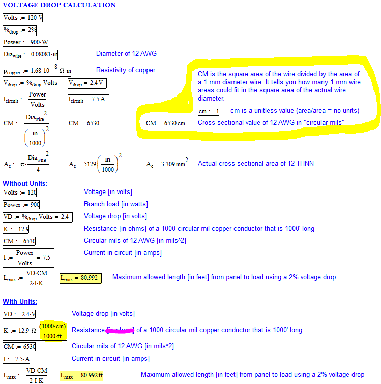
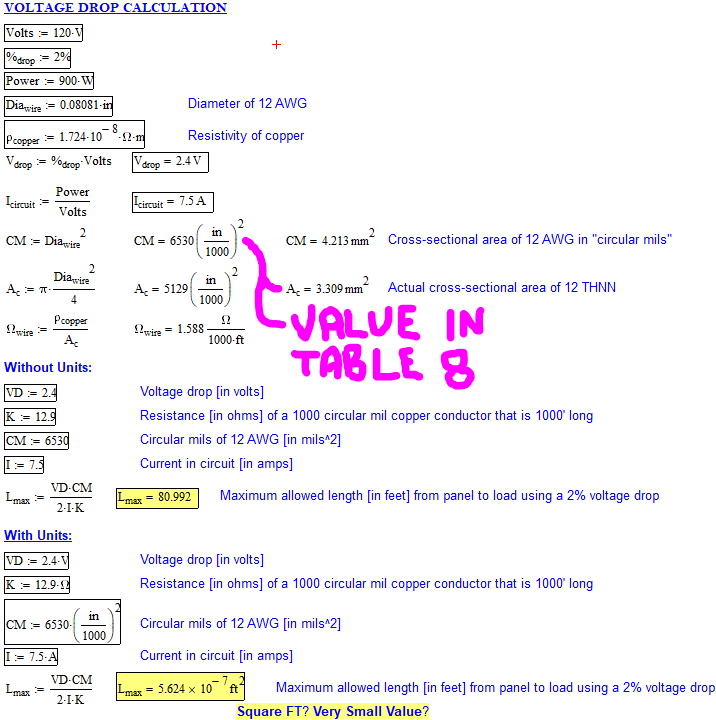
VD = 2*Length*Load*K / CM
Therefore Length= VD*CM/(2*Load*K)= 2.4*6530/(2*7.5*12.9) = 80.99 feet... easy.

Where:
[ul]
[li]VD = voltage drop = 2.4 (120v * 2%)[/li]
[li]Length = solved value in ft[/li]
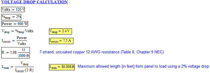
[li]K = 12.9 Ohms (found via several google searches, don't know how it is derived or where to find this value in NEC). I have found that resistivity of copper is 1.724x10^-8 Ohm*meter @ 20 degrees C, but I can't correlate this into the K value @ 75 degreees C.[/li]
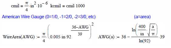
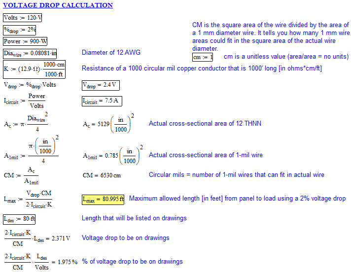
[li]CM = Circular mils = 6530 for 12 AWG (I understand this is the wire diameter squared, so this should be in [in/1000]^2). However, in Table 8 of Chapter 9, the area column is given in mm^2 and Circular mils and converting one to the other does not result in the same value.[/li]
[/ul]

However, if you include the units in the equation, the equation spits out a value of area instead of length. How can EE's work off of equations where units don't cancel out? I'm going crazy trying to figure out how to resolve the answer if I leave the units in the equation. Besides that, I'm struggling to understand K (how to calculate it or where to look it up). Has the NEC and/or the internet values I found actually have the units I described or is there some weird short-hand going on like when people talk about their tire pressure and they say 40 pounds instead of 40 pounds per square inch?

Capture_zqtgtc.png


Juston Fluckey, SE, PE, AWS CWI
Engineering Consultant
 
Replies continue below

Recommended for you

#12 AWG has an area of 6530 cm, not 6530*(in/1000)^2. One circular mil is the area of a wire 1 mil (1 in/1000) in diameter.

I developed the following Mathcad custom units and functions to help keep things straight:

Wire_Calcs_loksn0.png
 
jghrist,

First, thanks for the key to understanding!

Ok, so my variable 'CM' doesn't have a unit of area. 'cm' is basically a new unit that represents how many defined areas (area of square wire with 1 mil edges) are within an area. So it is unitless because it is square area (using actual wire diameter as leg length) divided by defined square area of (in/1000)^2. I also think I had the wrong units of K and with this new definition of the unitless 'cm', I think I have it all resolved. The units of 'K' should actually be Ohm*1000cm/1000ft and the 1000's cancel out to leave you with Ohm*cm/ft and 'cm' is defined as unity, so it further reduces to Ohm/ft.

Capture_ucdv8d.png


Juston Fluckey, SE, PE, AWS CWI
Engineering Consultant
 
For posterity, below is what I reduced my calculation to. I realized that 'CM' can be cross-sectional areas of actual wire and 1-mil wire. You don't need to use the square areas of each, or you can... the end result of the ratio will be the same. I understand why they simply use the square areas though since the ratio of circular area over circular area will have the 'pi' and '4' values cancel out and you are left with dwire^2/1-mil^2 (i.e. square area over square area). I cleaned up my comments in the calculation too.
Capture_jiieii.png


Thanks again jghrist for explaining the CM value.

Juston Fluckey, SE, PE, AWS CWI
Engineering Consultant
 
I get this:

Buildings require building wiring.
That means Romex or conduited THHN or similar.

Those need to be a minimum of 14AWG unless it's a commercial space which requires 12AWG minimum.

Doing a mess-O-math to come up with an unuseable size wire is not too useful.


14AWG wire is 0.002525 Ω/ft

twice that is the round trip, "dropping resistance"
0.002525 Ω/ft x 2 = 0.00505 Ω/ft

2% of 120V = 2.4V

7.5A x 0.00505 Ω/ft x L ft = 2.4V

L ft = 2.4V / (7.5A x 0.00505 Ω/ft)
L ft = 63ft of 14AWG
or
L ft = 2.4V / (7.5A x 0.00505 Ω/ft)
L ft = 100.8ft of 12AWG


Keith Cress
kcress -
 
itsmoked,

You are using Ohm's law which I think is easier (at least more intuitive to me) if you know where to get the appropriate design resistance (0.002525 ohm/ft for 14 AWG in your example). I don't know where to get these values. Also, I don't know if the Ohm's law approach is acceptable for calculating voltage drop vs the circular mil method. I have used the circular mil method in the past (without understanding the units) and it was accepted by plan reviewers. So, I'm sticking with that method unless I knew otherwise. Using my calculation above and back tracking to get the round-trip resistance for 12 AWG, I get 0.00395 Ohm/ft. Maybe these approaches are equivalent, just a matter of formatting the equations and variables. My statement would be true if your round-trip resistance (0.002525 Ohm/ft) is equal to 2*K/CM of 14 AWG. But regardless if they are the same or not, I now know where to get 'K' and 'CM' values, but I don't know where to look up the resistance value you gave. If the correlation is truly 2*K/CM, then I might as well still use the circular mil equation since I have to look up K and CM anyway. However, if there is a table of AWG resistances per ft, I would interested in changing my approach and I would ask why they decided to break one variable (resistance per ft) into two variables: K and CM? Again, Ohm's law is simple... just tell me what the design resistance value of the 12 AWG wire is NEC!

Juston Fluckey, SE, PE, AWS CWI
Engineering Consultant
 
Dear Mr. P1ENG (Structural)(OP)
The main issue had been answered by learned contributors.
I wish to add the following for your information:
1. NEC states VD for (a) [branch circuits] not exceeding 3% and (b) [max total on both feeders and branch circuits] not exceeding 5%.
2. For VD, computation see NEC Article 215-2....with basic formula
VD = (2xLxRxI)/ 1000 (volt)
where: L=one way length of circuit (ft),
R= conductor resistance in ohm per 1000ft at 75[sup]o[/sup] C . See Chapter 9 Table 8,
I= load current (A)
3. Chapter 9 Table 8
(a) AWG or kcmil 14, 7 strand, uncoated copper 3.14 ohm/1000ft, or 1 strand uncoated 3.07 ohm/1000ft,
(b) AWG or kcmil 12, 7 strand, uncoated copper 1.98 ohm/1000ft, or 1 strand uncoated 1.93 ohm/1000ft.
With these data, they simplify the computation, see 2. above.
Che Kuan Yau (Singapore)
 
che12345,

Thanks for your input! As I now understand the units, this is becoming easier to comprehend. I understand NEC has the 3%/5% limits as you stated. I think the 2% that I am using came from ASHRAE. The 1.98 Ohm/1000 ft value of the 12 AWG, 7 strand, uncoated copper aligns nicely with the K/CM value I am using in my calculation snippets above. You are correct, that using the Ohm/1000 ft would simplify my equation as shown below and now I'm back to Ohm's law!

Capture_jxysfq.png


Juston Fluckey, SE, PE, AWS CWI
Engineering Consultant
 
Dear Mr. P1ENG (Structural)(OP)
FYI: the Ohm's law method simplified the computation.
This is used in UK see BS7671 and also in the IEC world; in SI units.
The Length is in meter, cross-sectional area is in mm[sup]2[/sup]. The VD is in [mV/A/m].
Che Kuan Yau (Singapore)
 
Status
Not open for further replies.
Back
Top