Hi,
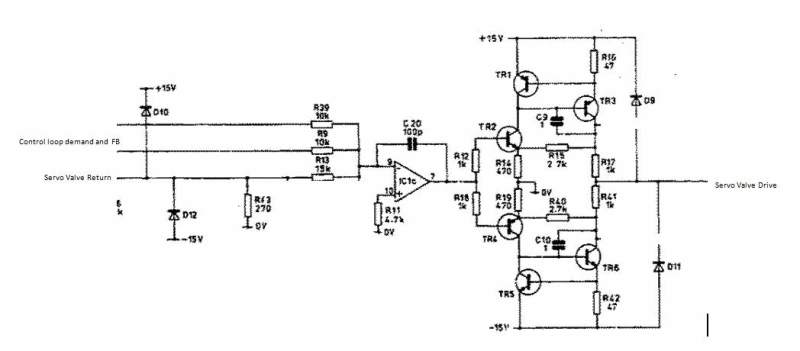
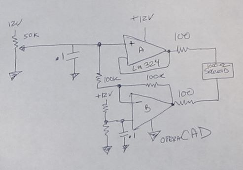
I'm looking for a power control circuit (supply) to drive a -8mA to +8mA electro-hydraulic servo. Previously, I've used a power supply set to limit current to 8mA, with a reversing switch to reverse polarity, but this seems so Flintstones. I've been looking for a way to have a single dial analog control to sweep from -8 to 0 to +8mA but having no luck.
The biggest problem so far seems to be the 1000 Ohms resistance of the servo. I tried using a signal conditioner configured to 0-20 mA, controlled to 8mA, and connected to the servo to in reverse polarity give -8mA, then use another signal conditioner configured to 0-20 mA and controlled in the 0-16 mA range via a pot and connected in straight polarity, with the thought that the 2nd supply would cancel out the 1st as I swept its control from 0 to 8 mA, thereby creating a -8 to 0 mA control, then as I swept it further to 16 mA, would get net 8 mA in the + direction. Turns out they require an output resistance <600 ohms, so that didn't work. The 2nd unit won't drive more than 15 mA through 1000 ohms, and when I paralleled them together (with a dummy 1K ohm load), neither would produce more than half the current they had when connected alone.
So, I searched for online resources for bipolar current sources, but all of them I found were limited to output resistance well less than my 1K Ohm.
I ordered a couple of cheap LM317 based regulator boards off ebay and plan to experiment with them configured as constant current sources to see if I can do something like above (except successfully), but using one as a constant 8mA supply driving the servo in the (-) direction, then introduce the second one to drive current in the opposite direction through 16 mA for a net -8 to +8 mA sweep. I may alternately have to use them as constant voltage sources, (one being static, one being swept) as that may be key to achieving success. Not sure yet. I may end up using one as CC, one as CV swept.
Can anybody point me to a very simple circuit I can build, or an off-the-shelf solution where I can sweep a dial to get a continuous sweep of -8 to 8mA through a 1KOhm load?
Thanks,
Ed
Edit: Forgot to mention I'm a Mech Eng, with some advanced Technician level Electrical/Electronics knowledge (for an M.E.) (Anti-Tank Missile Systems Tech, USMC, late '80's)


