Eng-Tips is the largest engineering community on the Internet

Intelligent Work Forums for Engineering Professionals

Need drive sprocket design help

Status
Not open for further replies.

nebdirtturner

Automotive
Oct 5, 2014
7
0
0
US
I am designing a drive system using snowmobile tracks as drive components. The issue I have is that I need drive sprockets that are larger than currently manufactured. Let me give you some specifics on the components I am utilizing.

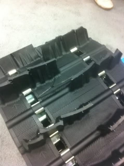
The snowmobile tracks have a 2.52" pitch with 1.5" square windows for the sprocket teeth to engage. The rollers on snowmobile tracks are not round they are elliptical they are 0.5" thick and 1.0" long.

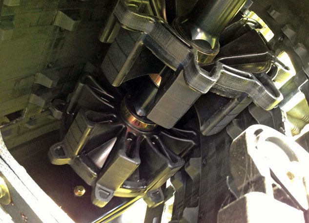
The only limiting factors of the sprockets are that the bottom diameter must be at least 12" for clearance of the drive lugs on the inside of the tracks.

I have laid out a sprocket already and had a sample one cut to see if it works. If the track is laid out flat it engages all the windows appropriately and works correctly. However the sprockets will have the track wrapped around them 180 degrees (think bulldozer drive sprocket arrangement). When I wrap the track around the sprocket it fails to engage correctly and after about 90 degrees of motion the track rides up the tooth and jumps.

I originally thought this would be an easy part of my design but now I am second guessing myself. I do not if my angles are incorrect or the issue lies in the fact that a snowmobile track is not rigid like the link design of chain and therefore going around in a circle the pitch actually gets smaller than 2.52" because of this "bend in the link". I do know that snowmobile manufacturers use drive sprockets for tracks I would gladly purchase the sprockets from them but they are way too small in diameter for what I need.

Any help would be appreciated!
 
Replies continue below

Recommended for you

Try making a couple of plain round untoothed plywood disks of your desired base circle diameter, and cast a tooth or two, e.g. with plastic wood or something, directly from a window.

Come to think of it, the base circle diameter cannot be arbitrary. Remember that the real pitch circle must lie approximately in the central plane of the belt. Try a little reverse engineering of the OEM sprockets and work from there.


Mike Halloran
Pembroke Pines, FL, USA
 
nebdirtturner-

Based on your description it sounds like your drive sprocket might look something like this. If so, the tooth profile will likely change when you increase/decrease the number of teeth (and pitch diameter) of the sprocket. While the circumferential spacing at the pitch diameter remains constant as the number of teeth increases/decreases, the angular indexing/spacing between teeth does not. So the profile of the teeth must adjust to compensate for this effect.

In order to generate teeth having the correct profile on your larger diameter drive sprocket, you'll need to first figure out what geometry the original sprocket teeth were based on. But even if you have this information, calculating the exact tooth profile needed for your new sprocket may be no simple task. Ultimately, it might be much easier to find a company that has the capability to design and manufacture the sprocket for you.

Good luck to you.
Terry
 
Thanks for the input gents. Unfortunatly I am unable to view photobucket pics on my computer so I don't know what your ptooth profile looks like. I was able to find a free online sprocket designer that would allow me to download the CAD file of any sprocket you input the parameters for, it is called sprocketeer. It gave me a 2D rendering that I checked dimensionally against the one I designed. My angles are all correct for the teeth so I got that correct. However the bottom diameter of mine was 0.2027" larger radius and the pitch diameter was also that much off. I don't bleieve that this is my only issue because the teeth do not engage the track as they are supposed to on mine.

Now I suppose you are wondering why not just use the remdering? Well I would love to but the teeth would extend about an inch past my track and would impale themselves in the ground or chew up anything that the machine is operateed over. That is why I was desiging a sprocket with blunt teeth that are only 0.75" tall so they wouldn't extend past the face of the track. Aparently it is possible here is a pic of one. What do you think?
 
 http://files.engineering.com/getfile.aspx?folder=1f0532a6-9f98-42c3-9ebe-aaccdc92e7f4&file=mine.jpg
Mike just pondering your solution, I have tried that actually that was my first attempt (multiple) but then I figured out that you need to know the appropriate base circle diameter to begin (for your cut out). So I took my pitch 2.52" inches and multiplied by my tooth count (14) and came up with a circumference of 35.28" a diameter of 11.23" and thusly a radius of 5.6150". That is what my CNC sprocket was based off of, however that one didn't work, so I don't know how making another blank will work, if you see where I am going.

I feel that I have one of two problems or both working against me, first is the material my "chain" is made of. The links of my rubber "chain" flex or curve around the circumference of my sprocket so I believe the pitch is narrowing as it goes around the sprocket, throwing my tooth pitch dimensions off.

The second issue might be the approach of the tooth itself. Most drive sprockets have a pointy concave profile like on a bike or a convex design like the one in my sprocket from Sprocketeer which forces the links apart at the rollers keeping the chain in a straight segmented orbit around the sprocket. Maybe if I made the tooth "less wide" or made it with a smaller crown it would insert itself in the windows and make the track behave more like a chain, and my math is in fact correct I just have too much junk in my proverbial trunk. What do you think?


You can't use the exact equations for a chain, because the chain links remain straight as the chain flexes over a sprocket.

... whereas, the belt curves as it flexes over a sprocket, so the pitch line of the belt on the sprocket is part of a circle, whereas the pitch line of a chain on its sprocket is a polygon.

So basically, you have to account for the difference between the length of an arc between adjacent belt holes, and the chord associated with that arc.

Be careful: the arc is at the pitch radius, in the central surface of the belt (or at the radius of any internal reinforcing cables), not at the base circle of the sprocket.


Mike Halloran
Pembroke Pines, FL, USA
 
nebdirtturner- Here's a picture of the type of sprocket I was describing:

images


This type of sprocket drives the track by the tooth flanks engaging bridges between pockets in the track, similar to what you described. The bridges in the track typically use some sort of metallic insert/facing to provide a durable contact surface, as shown in this picture:

camoplastpeakstrack.jpg


As MikeHalloran pointed out the tooth profile used for roller chain sprockets is not going to work for your application, since the kinematics of a roller chain with rigid link plates are not the same as those of a flexible toothed belt. You must consider how the belt is radially constrained about the sprocket axes of rotation. Are there any other (cylindrical) features coaxial/adjacent to the sprockets that contact the inner surface of the belt so that the belt follows a precise circumferential path around the sprocket? This arrangement allows the tooth contacts simply to drive the belt rather than also constraining it radially.

Lastly, it is quite possible that the exact profile of the sprocket teeth required to match your track might be some geometry proprietary to the track OEM. The tooth profile would need to provide a smooth and consistent approach/recess motion with the surface profile used on the metal track bushings. The track bushing profiles are probably optimized to minimize contact stress and produce a specific pressure angle at the sprocket tooth contact. These factors are very important if you wish to get good performance from the track and sprocket system.

If you know who the track OEM is you might try doing a search for any patents they have filed covering this field. The patent filings might provide some details of proprietary designs.

Good luck to you.
Terry
 
You all bring up very good points; I was figuring track flex was the culprit. When designing the sprocket only the bottom surfaces of the rollers will be in contact with the sprocket. The tooth will extend high enough to drive the track for forward and reverse propulsion and will also keep the track from jumping the sprockets laterally. I did some research on toothed sprockets made for snowmobile track; they all appear to be able to be used on different makes of track as long as they are the same pitch of track. Therefore it appears as though there are no proprietary design considerations to take in to account when designing the sprocket.

The track (one like it anyway) is the photo attached I will have two sprockets (one each per row of windows) that will engage the lugs between the windows if it were a chain they would be considered the roller. So only the bottom surface of each lug will be in contact with the sprockets, the span one each side of the windows will not be supported or touch a sprocket in any way. I need to figure out what calculations the manufacturers used to make these sprockets; someone out there has the conversion factors for rubber track versus metal chain. I may take my current incorrect sprocket and start removing a uniform amount of material from the tooth profile until everything fits, then uses those measurements for the new sprockets.

These sprockets will be used in a low speed environment with a maximum speed of 4 MPH of travel.

PS how do you put a pic in your post instead of having to use the attachment button.

Thanks everyone!
 
 http://files.engineering.com/getfile.aspx?folder=90abc0a0-e3a2-4f6a-9cff-8b432d7abba5&file=track.jpg
Are you sure your track does not require the type of cylindrical surface features shown adjacent to the sprocket teeth in this picture?

Yamaha-Viper-Extroverts.jpg


These cylindrical surfaces are not contiguous but they still force the track to follow a path around the sprocket that is very close to circumferential. Without them the track follows a path around the sprocket similar to what you would see in a conventional roller chain.
 
Tbuelna, I haven't seen a sprocket quite like that but this is why I believe they are making that sprocket that way. Snowmobiles drive the track in one of two ways. In addition to running a regular sprocket like what we are all used to, the inside of the track also have lugs (you can see them in the pic)that extend down off the inside surface of the track as well. Many machines use a sprocket with recesses that engage these lugs, basically a negative image of a sprocket.

The ones that drive the track in a "normal" way with a toothed sprocket are called no slip sprockets, because apparently when the track starts to get worn it will begin to ratchet over the negative type sprocket and slip. I believe what you have a picture of is a hybrid dual drive sprocket that runs the track using the windows and the lugs.

I have attached a photo below of an external type snowmobile sprocket that does not have the extra appurtenance on the sides. I really think I have made the tooth profile to fat at the top and it just is not able to get into the window correctly.

I really gets my goat that these folks have it figured out to where they can manufacturer a sprocket and everything works great, I can't get past the drawing board.
 
 http://files.engineering.com/getfile.aspx?folder=34a607b5-c02f-4029-ad4d-3555a9f46e41&file=sprocket04-108-28_LRG.jpg
Status
Not open for further replies.
Back
Top