tatertots89
Mechanical
Hey,
I'm using a Mitutoyo crysta apex s574 with MCOSMOS GeoPAK software and am trying to figure out how to ensure that my probe hits are normal to the surface. As I understand it, the machine applies the tip compensation to the probe ball/tip in the direction the probe was travelling at the moment of contact. Up till now all measured features were on planes normal to the X,Y, or Z axis (relative to machine origin) which was easy to measure as you can easily move the probe in pure X,Y or Z movements, but now I need to measure features on compound angles.
To summarize my question, how do I account for the section circled in blue?
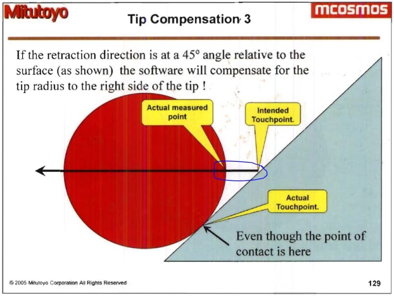
My thoughts are:
- If I measure an unknown plane with 3 points, the plane angle will be correct (if I drive the probe in the same direction for all 3 hits) but the plane position in space will be slightly off (due to tip compensation error shown above). BUT, once this angle is known, I can somehow drive the probe in the normal axis of the measured plane (with the determined angle) to then get 3 new data points and have accurate angle and position data for that plane.
- To accurately measure the position of a plane at a compound angle, I need to either hit the surface in a path normal to the surface, OR determine through trigonometry calculations how much to offset the measure data (based on direction hits were taken in, ball radius and angle of the plane determined originally by driving the probe at an unknown but consistent path).
Is this possible to do with my machine/software combination or do I need a different program? I want to be able to do this both automatically and manually. If you guys could share some insight or point me in the right direction it would be greatly appreciated!
I'm using a Mitutoyo crysta apex s574 with MCOSMOS GeoPAK software and am trying to figure out how to ensure that my probe hits are normal to the surface. As I understand it, the machine applies the tip compensation to the probe ball/tip in the direction the probe was travelling at the moment of contact. Up till now all measured features were on planes normal to the X,Y, or Z axis (relative to machine origin) which was easy to measure as you can easily move the probe in pure X,Y or Z movements, but now I need to measure features on compound angles.
To summarize my question, how do I account for the section circled in blue?
My thoughts are:
- If I measure an unknown plane with 3 points, the plane angle will be correct (if I drive the probe in the same direction for all 3 hits) but the plane position in space will be slightly off (due to tip compensation error shown above). BUT, once this angle is known, I can somehow drive the probe in the normal axis of the measured plane (with the determined angle) to then get 3 new data points and have accurate angle and position data for that plane.
- To accurately measure the position of a plane at a compound angle, I need to either hit the surface in a path normal to the surface, OR determine through trigonometry calculations how much to offset the measure data (based on direction hits were taken in, ball radius and angle of the plane determined originally by driving the probe at an unknown but consistent path).
Is this possible to do with my machine/software combination or do I need a different program? I want to be able to do this both automatically and manually. If you guys could share some insight or point me in the right direction it would be greatly appreciated!