Eng-Tips is the largest engineering community on the Internet

Intelligent Work Forums for Engineering Professionals

  • Congratulations waross on being selected by the Tek-Tips community for having the most helpful posts in the forums last week. Way to Go!

Need Help Modelling Tips

Status
Not open for further replies.

VN1981

Aerospace
Sep 29, 2015
186
0
0
IN
Trying to model a pressure bulkhead like this one

images_psuygq.jpg


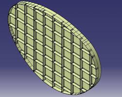
Basically, need some tips on modelling web stiffeners with minimal effort & time. I want to make the stiffener spacing parametric so if I need to make any changes in spacing, it would be easier. I am thinking of drawing all the stiffener lines in one sketch with dimensional constraints and use output feature for each lines and use ribs or pad features with thickness for solid modelling. Is there any better way of accomplishing the above?
 
Replies continue below

Recommended for you

I would make one vertical stiffener and then pattern it (making the spacing parametric). Repeat for the horizontal, or just rotate the vertical pattern. Trim the stiffeners with a Pocket of the bulkhead shape.
 
Firstly, I want to thank many members who are helping others (like myself) with helpful answers. Really appreciate the value provided by this forum.

I have a couple of questions and I did not want to start a new thread.

1. Lets say when I am doing a multi-section loft in GSD if I use guide curves, in the resulting surface I get a black internal line where the guide curve passes. Is there anyway to get rid of the this black line later? This black line presents an issue for many downstream operations and we would like a clean surface. I know Surface Simplification tool can get rid of them internal blacklines but for surfaces which are quite complex & curved, I have observed that resulting simplified surface quality is not good. When I run any kind of surface quality checks I can see lots of chequered boxes (especially in highly curved regions). Hoping that members can point out to any tool which can be used to achieve the above.

Screenshot_20210904_180412_xf585u.png


2. This question is regarding Part modeling procedure. I need to create skin pocket regions between spar & rib boundary lines. The issue is that skin is highly curved. I am including pictures which will hopefully give an idea of what I am trying to do. Purple lines are rib flange boundary lines & similarly green lines are spar flange/cap boundary lines.

My modeling thought process was that I will extract the spar & rib boundary lines from part and join them and make a curve offset of the join.

Screenshot_20210904_182401_tmr0xp.png


I will then offset the skin from OML and use pocket feature to remove material till the offset surface. Issue is that pocket or pad needs a sketch based profile and won't accept curve offset.

Screenshot_20210904_182745_rlotix.png


I need to create around 15 pocket regions through out the wing (30 if I include both top & bottom skins) and I am hoping for a procedure which is easier and hopefully parametric.

Will really appreciate any pointers.

Thanks in advance folks...
 
Answer to question 1: NO way to remove the "black line" it is a soft edge in the definition of the surface and limit internal faces. What is the impact downstream?

Answer to Question2: Pad and Pocket are based on profiles, usually defined by Sketches, but if you have several curves in 3D and those curve defined a 2D profile then you can Join then and use the Join for Pad / Pocket. If the profile is not planar you could make a surface/volume (in GSD) then use this with a closed surface in PartDesign and remove the feature using boolean operation.

Eric N.
indocti discant et ament meminisse periti
 
itsmyjob, thanks for your replies. Sorry for my late response.

1. Mainly concerned with aesthetics of surfaces (of course these internal soft edges can be hidden using View mode 3) but any internal edges are "transferred" to any downstream modeling (for ex: if the current surface with edges are used as parent for all children operations). Also, when we export the geometry for CAE operations using neutral formats, due to these internal edges, the surfaces are split in to patches which needs to be cleaned up again. Mainly are they requesting for a clean geometry.

2. I am not sure if I've tried a Joined curve as an input for pad or other sketch based features but I will try it out. Thanks for your suggestions. I really appreciate it.

 
In Generative Sheetmetal Design workbench, what are the differences between "wall on edge" & "flange" commands?

Up on some research, I think one of the difference is that in flange command, the radius of the bend can be modified while in Wall on Edge, the bend radius is taken from the sheetmetal parameters spec. I think there are more options in Flange that I need to look up (like Flange positioning can be modified using user specified plane etc)
 
Status
Not open for further replies.
Back
Top