Hi!
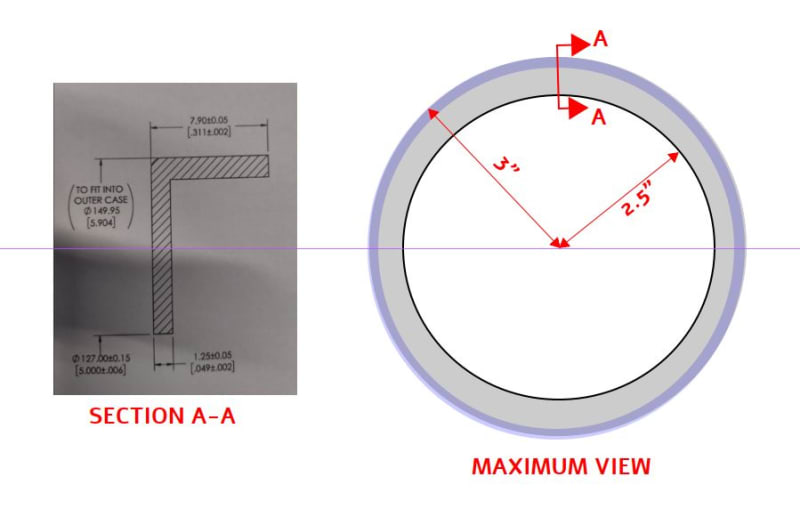
Can someone please help me calculate the surface area of the below elements?
[URL unfurl="true"]https://res.cloudinary.com/engineering-com/image/upload/v1706032543/tips/Nowy_obraz_mapy_bitowej_ygg7td.bmp[/url]
[URL unfurl="true"]https://res.cloudinary.com/engineering-com/image/upload/v1706032660/tips/Nowy_obraz_mapy_bitowej_lc5ib8.bmp[/url]
[URL unfurl="true"]https://res.cloudinary.com/engineering-com/image/upload/v1706032925/tips/Nowy_obraz_mapy_bitowej_ultwau.bmp[/url]
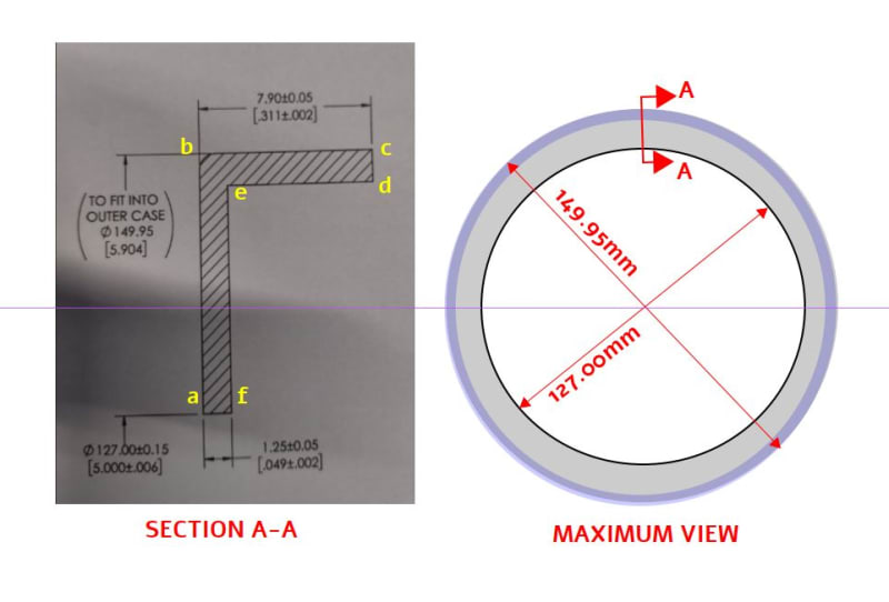
![[lol]](/data/assets/smilies/lol.gif "[lol] [lol]")