Hi All,
At my workplace, there is an 34.5 kV subsea distribution cable that is 30 km long, connected to WIDP01 and KARA01 bus.
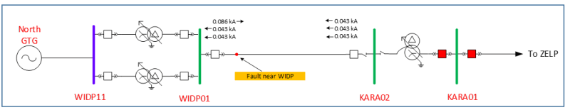
Both WIDP01 and KARA01, have generators connected at a voltage level of 13.8 kV (generator at KARA01 is not shown in this drawing), where the transformers used are Dy transformer.
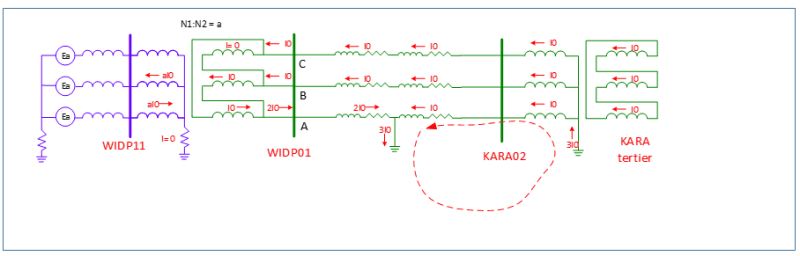
Based on simulations and actual cases, no zero sequence current can be detected at bus WIDP01, because there is no ground reference at WIDP01 bus.
I plan to add directional negative sequence current protection to bus WIDP01 to detect line to ground fault. Based on the simulation, negative sequence current can be detected at bus WIDP01. The Negative sequence current should be I0.
I need some input, can this protection mode be applied? Because I haven't found many references regarding this type of protection mode
What are some of the potential issues that may arise that I need to consider when implementing this?
As a note, power flow can flow from bus WIDP01 to bus KARA01 and vice versa
Thanks,
Angga
At my workplace, there is an 34.5 kV subsea distribution cable that is 30 km long, connected to WIDP01 and KARA01 bus.
Both WIDP01 and KARA01, have generators connected at a voltage level of 13.8 kV (generator at KARA01 is not shown in this drawing), where the transformers used are Dy transformer.
Based on simulations and actual cases, no zero sequence current can be detected at bus WIDP01, because there is no ground reference at WIDP01 bus.
I plan to add directional negative sequence current protection to bus WIDP01 to detect line to ground fault. Based on the simulation, negative sequence current can be detected at bus WIDP01. The Negative sequence current should be I0.
I need some input, can this protection mode be applied? Because I haven't found many references regarding this type of protection mode
What are some of the potential issues that may arise that I need to consider when implementing this?
As a note, power flow can flow from bus WIDP01 to bus KARA01 and vice versa
Thanks,
Angga