Continue to Site

Eng-Tips is the largest engineering community on the Internet

Intelligent Work Forums for Engineering Professionals

  • Congratulations IDS on being selected by the Eng-Tips community for having the most helpful posts in the forums last week. Way to Go!

Neutral Current calculation in two star connection in LC Filter circuit 2

Status
Not open for further replies.

afzumannu

Electrical
Jul 1, 2011
93
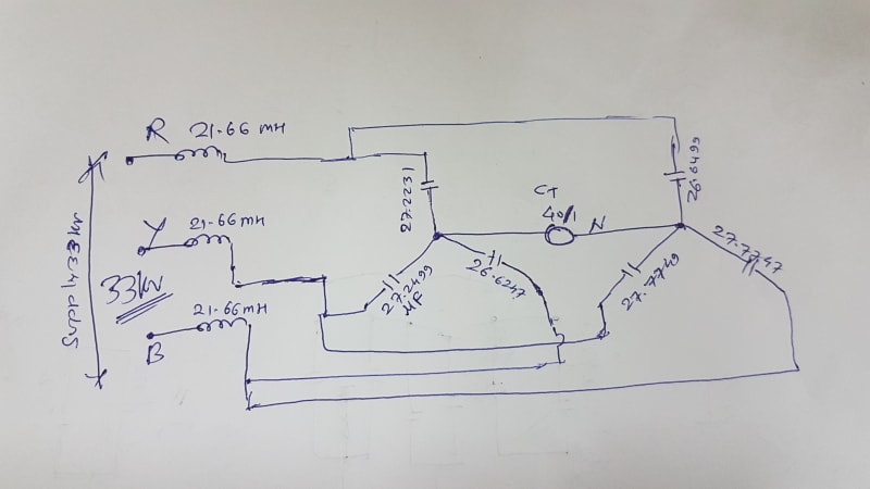
We have 3 phase LC Filter circuit 21.66mH per Phase also the Capacitance value in all 6 Branches which are Xc1 = 27.2231µF, Xc2 = 27.2499, Xc3 = 26.6247 ( one star group), Xc4 = 26.6499,Xc5 = 26.7749, Xc6 = 26.7747(2nd star group), i want to calculate the Neutral current for unbalance protection. supply voltage is 33 KV. Please suggest me the correct formula for calculation. please see the attached Diagram.
150HZ_cfgq5g.jpg
hand_make_lq2t0n.jpg
 
Replies continue below

Recommended for you

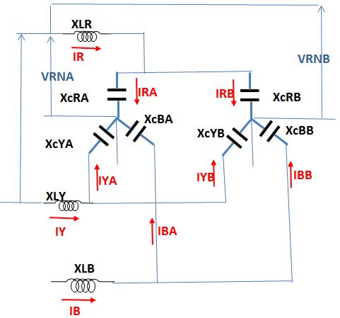
From these equations calculate IR, IRA and IRB:
IRxjXLR+IRAxjXcRA-IYAxjXcYA-IYxjXLY=VRY[>0]
IYxjXLY+IYAxjXcYA-IBAxjXcBA-IBxjXLB=VYB[>-120]
IRxjXLR+IRBxjXcRB-IYBxjXcYB-IYxjXLY=VRY[>0]
IYxjXLY+IYBxjXcYB-IBBxjXcBB-IBxjXLB=VYB[>-120]
IR=IRA+IRB
IY=IYA+IYB
IB=IBA+IBB
IBA=-IRA-IYA
IBB=-IRB-IYB
And finally VRNA=IRxjXLR+IRAxjXcRA and VRNB=IRxjXLR+IRBxjXcRB
Filter_LC_unbalanced_cvterk.jpg
 
@ 7anoter4 it is Very tough for me I am trying to calculate anyhow, but if you can calculate it will be appreciable, I am not much perfect in equations..values I mentioned already and also I have to calculate neutral current between both star point.
 
@7anoter4, can you ease this equations, i mean can you clarify more and make it short please. thanx in advance
 
Replacing the 6 equations at the bottom in the 4 equations at the top we get
4 equations with 4 unkowns in complex numbers.Currents in A,impedances in ohm,voltages in volt.
[highlight #EF2929]IRA[/highlight]*j(XLR+XCRA)+[highlight #EF2929]IRB[/highlight]*jXLR-[highlight #EF2929]IYA[/highlight]*j(XLY+XCYA)-[highlight #EF2929]IYB[/highlight]*jXLY=33000
IRA*j(XCBA+XLB)+IRB*jXLB+IYA*j(XLY+XCYA+XCBA+XLB)+IYB*j(XLY+XLB)=33000*[cos(-120)+jsin(-120)]
IRA*jXLR+IRB*j(XLR+XCRB)-IYA*jXLY-IYB*j(XCYB+XLY)=33000
IRA*jXLB+IRB*j(XLB+XCBB)+IYA*j(XLB+XLY)+IYB*j(XLY+XCYB+XCBB+XLB)=33000*[cos(-120)+jsin(-120)]
By replacing the impedances with their values we obtain:

IRA*j8.15559+IRB*j8.165628-IYA*j8.155355-IYB*j8.165628=33000
IRA*j8.15559+IRB*j8.165628+IYA*j1631095+IYB*j16.33126=33000*[cos(-120)+jsin(-120)]
IRA*j8.165628+IRB*j8.155581-IYA*j8.165628-IYB*j8.155157=33000
IRA*j8.165628+IRB*j8.155157+IYA*j16.33126+IYB*j16.31031=33000*[cos(-120)+jsin(-120)]
cos(-120)=-0.5
sin(-120)=-0.86603
 
Since the impedances at both side [A and B] are close [ if this calculation was correct I did it using only excel!] then:
IR=-1167.35698159404-2021.93146923866i A [2334.723 A >-120]

IRA=-585.994985676536-1007.08007083315i A [1165.161 >-120.194]

IRB=-581.361995917505-1014.85139840551i A [1169.575 > -119.806]

VRNA=16500.0039327569-9526.18842883521i V [19052.52 >-30]

VRNB=16500.1434772235-9526.36160386728i V [19052.72 >-30]

DV=-0.139544466601365+0.173175032070503i [0.2224 V >128.86o ]

 
First a couple of comments:

- @afzumannu: don't post the same question twice, now you have two different posts regarding the same issue and different answers on each one (the other post: thread238-468015)

- This problem seemed pretty straightforward at first glance, you just need to solve the circuit, thats all. Easy, right?
Well, it's not that easy I can tell you. I'm strugling with it for a few days now (a few moments each day, to be honest). It's been a long time since I solve this kind of problems and it shows. It's a matter of honor at this point [evil]

Now back on track:

@7anoter4:
- Check the circuit you posted, it's laking the connection between star centers (the problem here is to find the neutral unbalance current between stars).
- When you solved the equations you forgot the capacitive reactances? 8.16 ohm its just the Xl for 60 Hz.
- OP never said it, but from the other post you can guess that OP's frequency it's 50 Hz. Can you confirm this, afzumannu?

I've solved the circuit, with one tiny little detail (two different ways, same results): I'm getting almost exactly twice the current beyond86 simulated with matlab (again, see the other post).

Line currents for 50 Hz (aprox 370 A):

Ir = 182.0875791+j318.1243825
Iy = 186.4995773-j320.6716509
Ib = -368.5871564+j2.547268414

Phase currents for star 1 (aprox 180-190 A):

Ir1 = 92.01248070+j160.7545872
Iy1 = 92.36007820-j158.8060369
Ib1 = -180.3976232+j1.246709657

Phase currents for star 2 (aprox 180-190 A):

Ir2 = 90.07509840+j157.3697953
Iy2 = 94.13949910-j161.8656140
Ib2 = -188.1895332+j1.300558757

And finally, unbalanced neutral current between stars:

In = 3.9749357+j3.195259957 (aprox 5.099 A)

But should be around 2.55 A?? (OP confirm this too, please!)
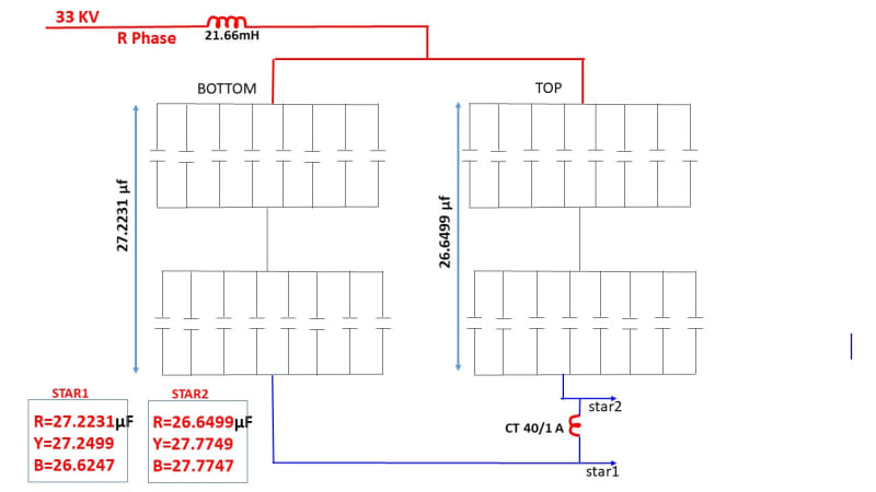
 
Both of you are great that you people are helping, @7anoter4: Frequency is 50HZ.
Yes @ argotier it is correct i posted it before with other threads.
because any how i want to get good formula where i can put the capacitive reactance and get the result
but the answer which @ beyond given which is matching almost 95% to real unbalance.
so the neutral current should be around > 2.5 Amp.

thanx @argotier & @7anoter4

i hope you will solve more easily and give me formula easiest one.

 
argotier said:
“When you solved the equations you forgot the capacitive reactances? 8.16 ohm its just the Xl for 60 H”
Worse, I divided by 10 ^ 6 instead of multiplying.
Because my excel [hand made] program allows the use of 4 * 4 determinants and no more I had to
consider that there is no current in neutral. All I could calculate is only the neutral voltage.

 
Sorry for the delay.COVID-19 problems[blush].
The calculation may be simplified indeed.
Because the general installation it is a star with non-draining neutral the sum of general currents IR,IY and IB equals zero.
Because there is a connection between the two star neutrals the capacitors A and B are parallel.
So IR*ZR-IR*ZY=VRY; IY*ZY-IB*ZB=VYB and IB*ZB-IR*ZR=VBR
ZR=XLR+XCRA*XCRB/(XCRA+XCRB) typical
By replacing IB=-IR-IY we get 2 equations with 2 unknowns: IR and IY.
Then using formula IRA=IR*XCRB/(XCRA+XCRB) [typical] we get IRA and IRB=IR-IRA.
The result is close to argotier result [±1-2%]
 
@7anoter4...Covid-19 everywhere dear, no problem, thanx that you are trying this much, but result should be around 2.5Amp, because in our relay coming unbalance according to the current, one of guy solved this using Matlab software..it was correct very fine. @ argotier sure we are very near to solve this something missing.
 
For the love of god I cannot find a complete solution. I'm giving up afzumannu [dazed]

I'm starting to think that this problem cannot be solved analytically and I don't have enough grey cells to perform a numerical approach with complex numbers.

Anyway this search for the "complete solution" was more a personal crusade than anything, as it would have involved a long complex calculation and you don't want that.

Sadly there is no single formula to solve this problem and the most simple way to do it is with the method 7anoter4 described, it's a simplified solution but it will give you a good enough result (once you divide it by 2). You can also make an excel spreadsheet.

Comparing this solution with beyond86 simulink results posted in the other thread for 3 different Cr1 values:

Cr1 - Simulink - Simplified method/2 - error%
27.2231 uF - 2.538 A - 2.549 A - 0.47%
26.8744 uF - 2.038 A - 2.004 A - 1.67%
26.9247 uF - 2.069 A - 2.081 A - 0.58%

 
@argotier, can you explain how you got the line current and phase current, please simplify it I mean IR and IR1 etc.
 

In my opinion, the difference is due to the CT 40/1 impedance. It seems to me the Simulink appreciate the CT impedance from data accumulated in its library.[I think here it has to be about 125 ohm]
 
@ argotier please send me how u calculated line currents, phase current etc. Explain in details or attach the file please
 
Finally it means nobody can solve by Manual calculation, only software possible? But I still believe that something missing all the solution possible by manual caculation.
 
If all the data are as you presented here a correct calculation can be done manually. However, since the result does not correspond to the actual measured it seems to me there is missing data: resistance [cables, capacitor tanδ, contacts, parasite resistance of the inductance and other] capacitance error? and other, and Simillink can appreciate it.
 
I think result should come without simulink too, that data I presented is enough, it means without software we can't get the real result..I still hope by excel spreadsheet we can get the result something is missing..
 
Hi Guys,
Still I am looking for the Manual calculation except Matlab for these capacitor banks neutral current. I am requesting @Anoter, @Argotier and others please come forward to solve this. also in my mind is it possible in manual then only we can work hard, otherwise it is waste of time and energy.
 
Eng-tips. Not Eng-solutions. You’ve been given tons of advice and not shown any attempt at finishing the solution your self. Time for you to start showing your work and to stop depending on others to do it for you.
 
Status
Not open for further replies.

Part and Inventory Search

Sponsor