Eng-Tips is the largest engineering community on the Internet

Intelligent Work Forums for Engineering Professionals

New VFD Failure

Status
Not open for further replies.

TugboatEng

Marine/Ocean
Nov 1, 2015
11,388
1
36
US
I feel like this is going to by a warranty issue so I can't disassemble further to get a more clear view of the cause but I present this story for any thoughts.

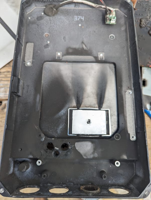
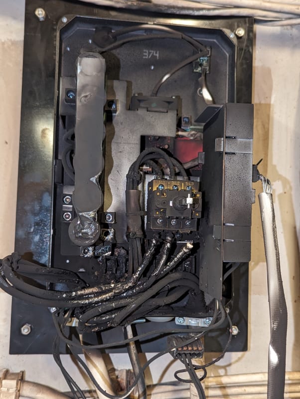
I installed a new 10hp, 480 volt VFD on a pump the other day. I tested and ran the pump for a short time while I got the parameters squared away. About 24 hours later while the drive was energised and NOT running this happened.

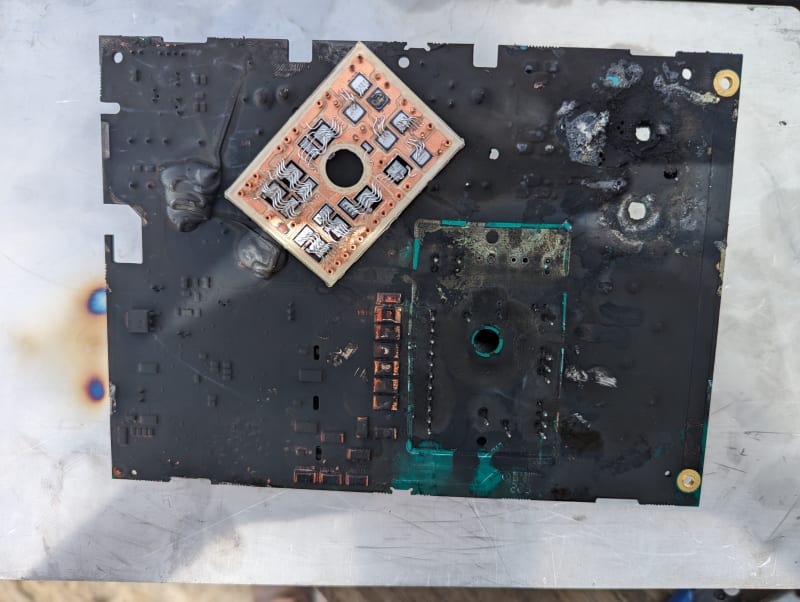
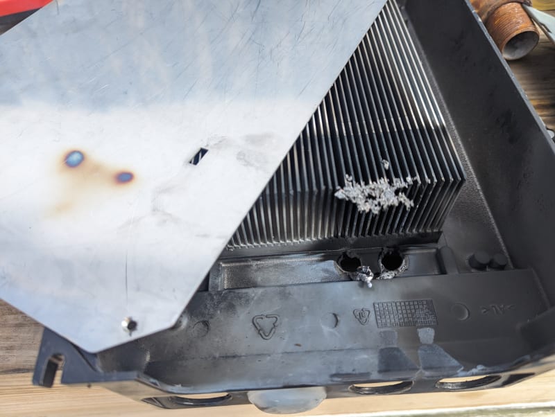
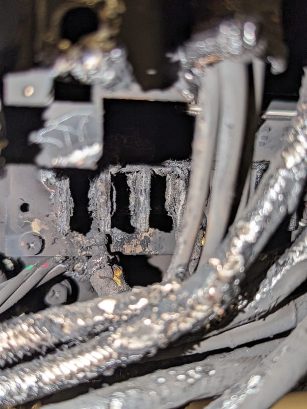
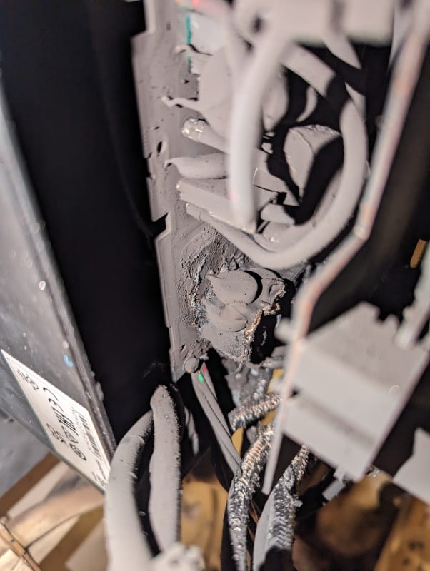
I'm curious, in the first picture it detonated one of the wires leading into the disconnect switch. It also detonated all 3 wires between the disconnect switch and the circuit board. It also burned the leads on the components in the final picture, they appear to be MOV's. The fault didn't clear a 40 amp breaker. The input wiring was 8 gauge and the 3 leads that failed were 10 gauge.

This failure is odd to me. I don't usually see all 3 phases go short circuit. This drive is in a high vibration environment. In fact, the 4 year old soft starter it's replacing died because all of its capacitors vibrated off the board and it appears one caused a reverse polarity event when it rotated around it's still connected lead. I mounted this one on soft mounts and was surprised to see a failure with 24 hours.

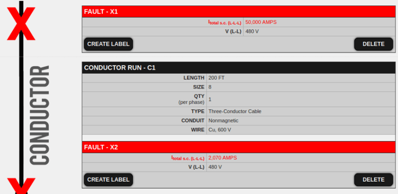
At the time of failure the system was being grid supplied through 60 amp current limiting fuses. It was a significant enough draw to brown out the vessel multiple times.

I also undersized the drive as the motor had no legible nameplate and I had to guess, incorrectly. During testing the motor pulled 14.5 amps and the drive is rated for 16 amps at ambient conditions.

PXL_20230828_173805368_lxnqar.jpg

PXL_20230828_173531921_k17uzj.jpg
PXL_20230828_173342000_lyhudc.jpg
 
Replies continue below

Recommended for you

The drive may have been on the shelf for too long when it was delivered.
A problem on large construction projects where there may be a year or two or more between delivery of the E-Houses and commissioning is the failure of capacitors.
Once an arc lights up, it can travel around inside the enclosure.
There are re-forming procedures for electrolytics to avoid capacitor failure.
Or it may have been something else.
Hopefully you will hear back from the warranty inspection.

--------------------
Ohm's law
Not just a good idea;
It's the LAW!
 
An arcing fault in an enclosure becomes a three-phase fault very rapidly. In 15kV class switchgear it can take less than a full cycle for an arcing fault to go from single phase to three phase.

Your "current limiting" fuses may take a long time to clear in a system with relatively low available fault currents. They can be current limiting at high fault currents, but they're not current limiting across all possible fault currents.

I’ll see your silver lining and raise you two black clouds. - Protection Operations
 
I'm not in a league with Bill and David on this stuff.

It does seem like an odd failure to me too, but like Bill says once it starts arcing all kinds of stuff can happen.

What originally happened inside the box to trigger the event sounds like the vendor's problem to figure out (Bill's theory is certainly plausible). What happens outside the box is your problem to figure out. The 40A breaker should've tripped on instantaneous, shouldn't it have? I'd be inclined to bench test that breaker and if the instantaneous passes, then David's comments bring to mind questions about available fault current.
 
What's the available fault current. Undoubtedly rather low.

I’ll see your silver lining and raise you two black clouds. - Protection Operations
 
At the time of failure the vessel was on shore power. I believe our 480V power is supplied by a 150kva pole transformer (can't see the nameplate from the ground). There is a 100 amp breaker, and 100 amp RK5 or 60 amp type J fuse fuse in the circuit. I don't think either of these would provide enough current limiting to prevent a trip of the 40 amp breaker. There is some 200+ feet of #8 cable in the loop. Perhaps that provides enough resistance for current limiting.
 
Do you happen to know the instantaneous setting of the 40A breaker?

Maybe it was selected on the basis of the onboard supply and the shore power has lower available fault current.
 
I have not had a chance to open the panel and witness the nameplate on the breaker. I will report back when that is available.
 
Perhaps that provides enough resistance for current limiting.
Did you mean impedance?
Maybe it was selected on the basis of the onboard supply and the shore power has lower available fault current.
Possible Pete, but not likely compared to generator power.

--------------------
Ohm's law
Not just a good idea;
It's the LAW!
 
Yes, impedance is what I should have said.

I don't know what the as designed generator power was. We've been downsizing our generators from 150kW to 99kW. That is something I never considered; reduced generator size may not provide sufficient fault current to trip breakers.
 
Using Bussman fault calculator, ignoring the fuses , and using the limited information provided (reference I estimate your fault current is around 2000 amps, which may result in slow clearing of either a fuse or a breaker. Current limiting fuses can further delay clearing, by pushing the fault current lower.
Screenshot_from_2023-09-02_10-05-01_hjsrdf.png

This is one reason current limiting fuses are not a shortcut to a solution for correcting available fault vs SCCR mismatch.
 
The manufacturer didn't want the drive back so I got to do an autopsy. Looks like a diode evaporated in the Power Integrated Module which created the initial arc flash to short the three line terminals. The flash sustained itself long enough to burn 3 holes completely through the aluminum chassis.


PXL_20230929_195133096_mtww1e.jpg


PXL_20230929_173629950_gjyrnn.jpg


PXL_20230929_195425465_v0oq3t.jpg
 
That may have been secondary to a DC bus capacitor failure, possibly even an MOV failure. Is it a 480V delta system by chance?


" We are all here on earth to help others; what on earth the others are here for I don't know." -- W. H. Auden
 
Normally our boats are ungrounded 480Y when on generator power. On shore power the boats are 480Y grounded neutral. The failure was found on shore power but it is possible the damage was done while on generator power.

Another note, in the marine industry metal electrical enclosure are bolted to the metal hull of the vessel. Bonding straps are essentially non-existent. This drive was isolated on a fiberglass adapter plate. The drive is mounted on a fuel tank and the fiberglass plate adapted mismatched bolt holes. Welding new brackets to fuel tanks gets expensive. The replacement drive has a bonding strap.
 
Status
Not open for further replies.
Back
Top