Eng-Tips is the largest engineering community on the Internet

Intelligent Work Forums for Engineering Professionals

No Penetration Boundary Condition in Modal FEM (Solving for Natural Frequencies)

Status
Not open for further replies.

Slagathor

Mechanical
Jan 6, 2002
129
0
0
US
We regularly perform FEA based Modal Analysis on what are essentially cantilevered vertical structures. The bases are bolted joints, and the real world interface between the sole plates and the structure are a can be a source of significant error. If we model as a bonded contact, the calculated stiffness (1st mode frequency) is always too high. It is considerably worse if the base flange of the structure bolted down is thinner. This is because in the real world, a no penetration condition exists. For many points in the contact interface region, for half the motion cycle they can pull away, but for the other half of the cycle they are pressing against the sole plate. It is "half stiff". The region of "half stiffness" is also always changing. It is not fixed. It is also dependent on the magnitude of modal excitation! If the structure is subject to a large exciting force, then more of the interface is half stiff for longer.

In static FEA analysis, a steady state "half stiffness" can be allowed for by using the "No Penetration" boundary condition. But in the FEA programs we have access to (ANSYS, Solidworks/Cosmos, MECWAY), none of them allow for the No Penetration contact in a Modal analysis. I expect this has to do with the underlying nature of FEM Modal analysis, in that you are effectively performing a dynamic analysis, and the boundary conditions for those nodes that are No Pen would change depending on the solution of eigenvalues and the time in the assumed Modal motion cycle. In other words, for each solution, you would have to iterate for the changing boundary conditions in the No Pen area, and it would take for ever to solve, if it ever would converge at all.

Am I off base here, or is there a FEA approach and Code that solves this problem of bolted joints that act differently vs time a load?

Thanks!

 
Replies continue below

Recommended for you

What is the ultimate goal of your analyses ? Do you just evaluate the natural frequencies or also perform other linear dynamics analyses based on these frequencies and corresponding mode shapes ?

In FEA software you can only include nonlinear contact in static simulation preceding the prestressed modal analysis. There are special techniques (like LCP in Abaqus) that make it possible to use nonlinear contact in linear analyses but only static, not modal ones.

Some research papers describe nonlinear modal analysis methods but they aren’t available in commercial software since they are used only for very simple models.
 
Thanks for the prompt reply.

We manufacture rotating machinery that is vertically mounted - somewhat tall and skinny with a fixed base mounting available. Avoiding operation near critical frequencies is very important to stop underlying excitation from amplifying, and causing high vibration. We also have to utilize vertical motors that are not generally customizable, so we are stuck with what is commercially available. A substantial portion of dynamic behavior is baked into the cake already with the motor. We can only go down from the starting point, which is the first natural frequency of the motor alone. Typically, specification requirements (our internal requirements, as well as in our industry) dictate that the first natural frequency be 20% below minimum steady state operating speed, or 20% above maximum steady state operating speed. We also have to sometimes worry about higher order modes, and whether they coincide with other exciting forces in the machine. For example, we may have an exciting force that is 2X, 3X or 4X operating speed in a machine. If we put the first natural below 1X min speed, we can actually run into issues with the the higher multiple exciting force (2X,3X,4X) exciting the 2nd mode of the machine frame structure.

Sometimes it is literally impossible to meet specification requirements given the speed range of the equipment, the fixed dynamic characteristics of the motors, and the underlying overall physics. Sometimes we are right at the edge of acceptance. If an analysis tells us that first natural frequency is 125% of maximum speed (we call this going high with all natural frequencies...which is always better and less complex), but the motor is actually softer than we were told, we can be at 120%, and have ZERO margin. This is unfortunately too common. Now, we have a real problem if the footing of the machine base is softer than we assumed because the boundary conditions in the FEA model OVER estimated the stiffness of the fixed surface boundary conditions.

We try to work around this issue by assuming partial restraint on the base. In other words, if the machine base has 4 ft^2 of footing to the base plate, we might assume that only 2ft^2 is actually a fixed boundary condition. We would locate these areas around the bolting, and "free up" the rest of the base, based on "touchy-feely" empirical experience. But this introduces error, and when we get burned, it can be VERY costly. I am talking tens or even hundreds of thousands of dollars.

It sounds like the "touchy-feely" approach is all there is.....
 
You can't directly include non linear BCs in a proper modal analysis, as the stiffness matrix would look decidedly odd and couldn't be inverted. But you can do a thing like a modal analysis, applying a sweep of sinewave force to the structure, and looking at the response. If you then 10x the amplitude of the force you will get a different result. This happens in the real world.

The flexure of base plates is very common and it has a huge effect on a cantilever.

Cheers

Greg Locock


New here? Try reading these, they might help FAQ731-376
 
SWComposites,

We are dealing with custom equipment in a highly competitive market. We use FEA to tell us how much to thicken baseplates, and whether to add gussets. Just saying "beef it up" does not work in the real world in a highly competitive market. Having very accurate FEA results is key to guiding our designs.
 
I didn't read the thread very carefully so the suggestion may be off so if I am not mistaken, how about running eigenvalue analyses intermittently as part of a nonlinear analysis in which contact is getting resolved?

*********************************************************
Are you new to this forum? If so, please read these FAQs:

 
Dear Slagathor,
The term "No Penetration contact in a Modal analysis" is supported long time ago with FEMAP & Simcenter Nastran, I understood any serious FE code will run the same way, please check.
With FEMAP we can run a pre-stiffened modal analysis, which is needed when using Linear Contact with normal modes/eigenvalue analysis (SOL103), simply adding a loading condition to your model by defining a SUBCASE.
Imagine a guitar string, the vibration natural frequency is dependent of the tensile load applied to the string.

Since modal analysis is essentially solving the differential equation of free-vibration, the load is not in the equation. So in normal modes/eigenvalue analysis (SOL103), the load is ignored.
There are two methods to take into account the surface-to-surface contact & pre-stiffened effect:
1.- Using STATSUB: Specifying the contact loading in a static subcase and including the STATSUB case control in the dynamic subcase will cause the differential stiffness to be computed and included in the normal mode solution.
2.- Running a nonlinear multi-step analysis (SOL401/402) including ANALYSIS=MODES in a subcase.
The modal subcase should include the METHOD case control command which selects the EIGRL bulk entry. The EIGRL entry defines the data needed to perform the real eigenvalue analysis with the Lanczos method. The modal subcase automatically includes the stress stiffening from the previous static subcase, and can potentially include follower stiffness and spin softening depending on the type of loading in the previous static subcase. The NLCNTL bulk entry has parameter inputs which allow you to control the stiffness contributions for the modal subcase. Also, param LGDISP needs to be specified to compute the differential stiffness, and NMLOOP should be a value not equal to zero so that the normal modes are computed based on the updated non-linear stiffness.

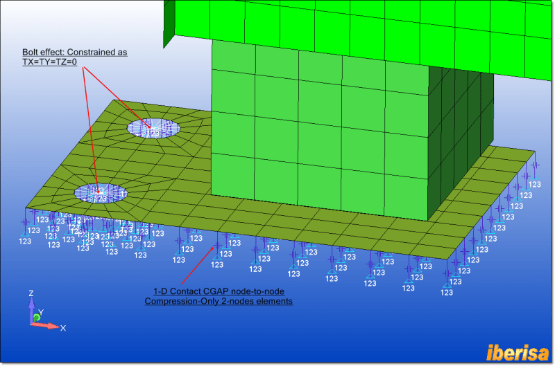
In my blog I explained in 2011 how to perform a normal modes/eigenvalue analysis (SOL103) of an assembly considering both surface-to-surface NO-PENETRATION contact and 1-D CGAP node-to-node contact elements, simply using method-1 via STATSUB:
In situations where contact "no penetration" effect (not boundary condition, please!!) can play an important role in the results of a linear static analysis then I include the effect in the FE model. For instance, here you have the "ground effect" in the base of a tank bolted to the ground. If not considered the contact effect all loadings gets transmitted to the ground only by bolts, that is more conservative.
detail_of_restraints_suy27b.png


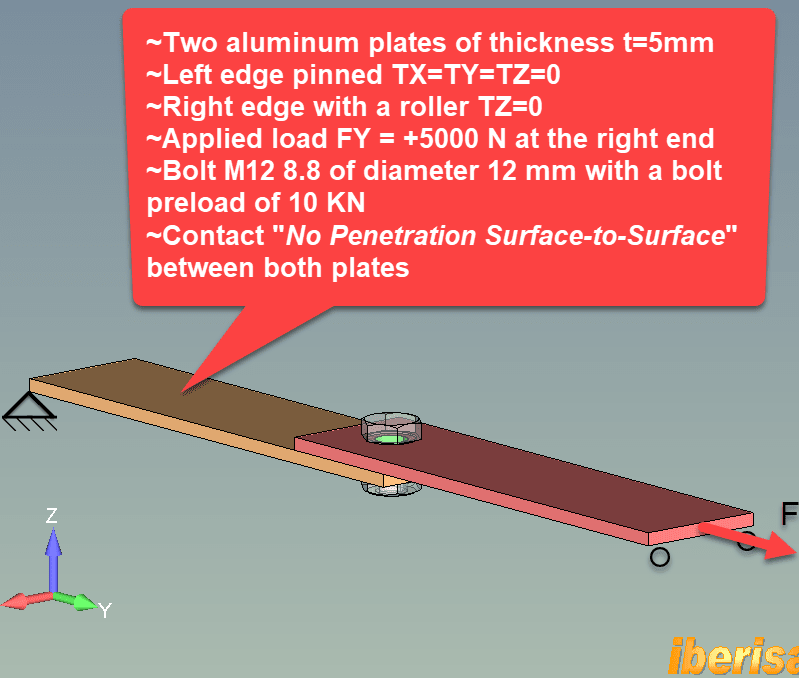
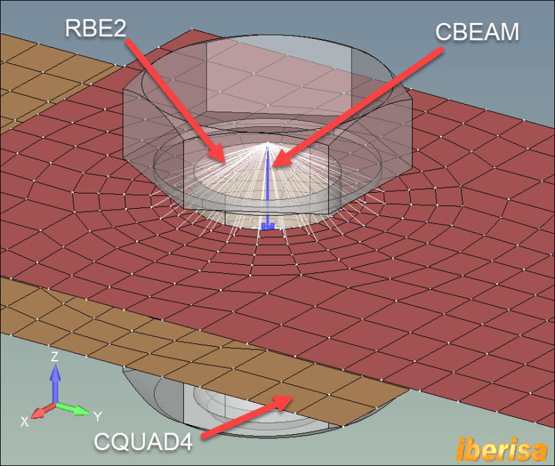
Also "because the pressure of the market" to explain how to consider the contact effect in preloaded bolted joints when performing a modal dynamic frequency response (SOL111) with FEMAP & Simcenter Nastran here you have a simply problem of two contact plates explained how to solve in my blog of FEMAP & Simcenter Nastran:

definicion-del-problema3_tlbnym.png

2placas-detalle-malla2_q2nvol.png


Enjoy!!.
Best regards,
Blas.

~~~~~~~~~~~~~~~~~~~~~~
Blas Molero Hidalgo
Ingeniero Industrial
Director

IBERISA
48004 BILBAO (SPAIN)
WEB: Blog de FEMAP & NX Nastran:
 
Status
Not open for further replies.
Back
Top