Hi all,
I am trying to run a simulation using the Abaqus/Standard solver on a cubic mesh with 1D truss elements using a steel material model. I want to apply a displacement-based boundary condition on nodes located on 1 face of the cubic mesh and a fixed boundary condition on nodes located on the opposite face of the cubic mesh.
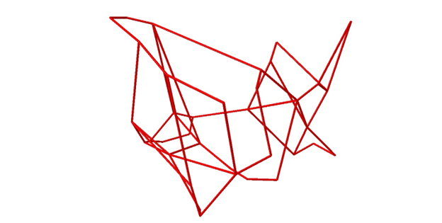
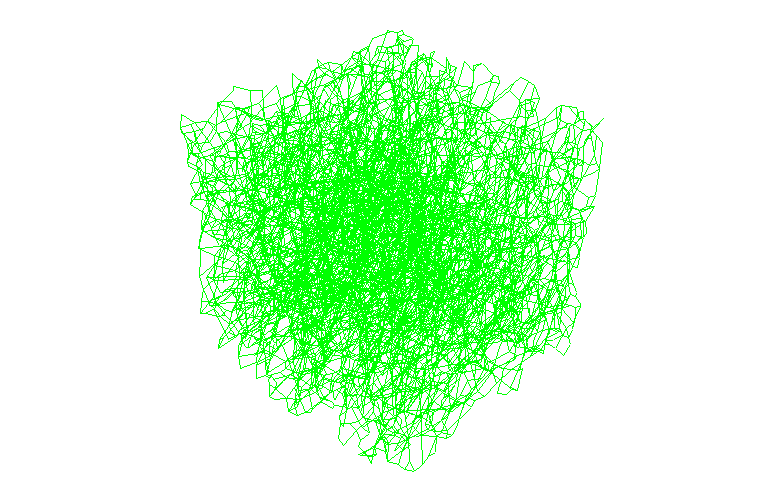
My simulation works for a small mesh (Image 1), but fails for a larger mesh (Image 2). I noticed that the simulation works for a larger mesh only if the displacement value is very small. When I view the results of this simulation, elements that are located very far away from my initial specified elements begin rotating freely. I expected all the elements of the mesh to incur a displacement only if I specified a displacement or an adjacent element was subject to a displacement, however this is not the case in my simulation.
Questions I would like to ask:
1. Am I missing some type of constraint in my problem to restrict the motion of connected elements?
2. Does each element behave individually, even though the mesh is imported as a single Abaqus part?
3. How do I analyze my mesh as a single steel part, rather than many steel trusses joined together individually?
I am trying to run a simulation using the Abaqus/Standard solver on a cubic mesh with 1D truss elements using a steel material model. I want to apply a displacement-based boundary condition on nodes located on 1 face of the cubic mesh and a fixed boundary condition on nodes located on the opposite face of the cubic mesh.
My simulation works for a small mesh (Image 1), but fails for a larger mesh (Image 2). I noticed that the simulation works for a larger mesh only if the displacement value is very small. When I view the results of this simulation, elements that are located very far away from my initial specified elements begin rotating freely. I expected all the elements of the mesh to incur a displacement only if I specified a displacement or an adjacent element was subject to a displacement, however this is not the case in my simulation.
Questions I would like to ask:
1. Am I missing some type of constraint in my problem to restrict the motion of connected elements?
2. Does each element behave individually, even though the mesh is imported as a single Abaqus part?
3. How do I analyze my mesh as a single steel part, rather than many steel trusses joined together individually?