Continue to Site

Eng-Tips is the largest engineering community on the Internet

Intelligent Work Forums for Engineering Professionals

  • Congratulations IDS on being selected by the Eng-Tips community for having the most helpful posts in the forums last week. Way to Go!

Noise Wall Foundation 1

Status
Not open for further replies.

Guest090822

Structural
Jan 18, 2017
260
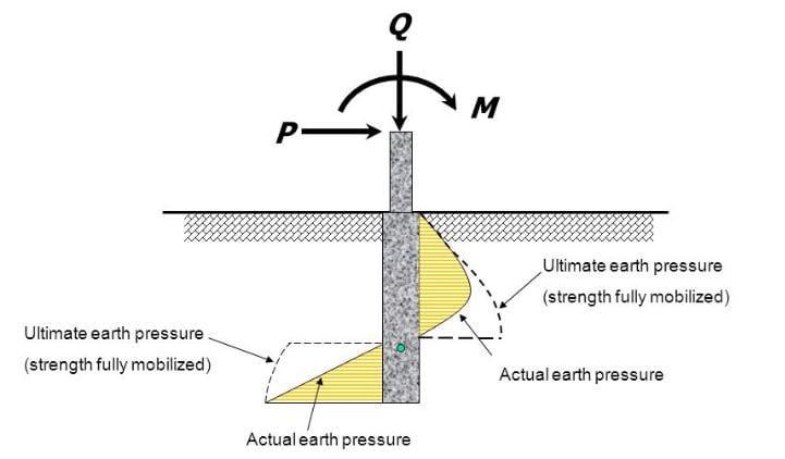
I’m checking a design for Noise Wall. The designer is using a simplified soil pressure distribution, I’ve attached a sketch. The foundations are essentially drilled shafts. The designer did something I’ve never seen before for this type of design. He took the area of the circular shaft, converted it to an “equivalent square” and then determined the embedment by summing the moments about the “toe”. I’ve always just used the center of the shaft and don’t normally account for the self-weight providing any passive resistance. I thought it was pretty practical, but my geotechnical coworkers went nuts over it and said it was too unpredictable to rely on. These shafts are spaced 12’ apart, and there are 200 of them. As a structural guy, I see this wall bending in only two directions (active to passive as shown in the sketch and then reversed if the wind blows in the opposite direction). That seems pretty predictable to me. I’m just curious if anyone else has seen the analysis done this way?
 
 https://files.engineering.com/getfile.aspx?folder=afd1fe0d-6355-45e5-b73b-3522a135ad03&file=B444066C-8D67-4351-B26E-73B2C35AEA09.jpeg
Replies continue below

Recommended for you

Have not seen anything like that before.

The shaft will rotate about a point somewhere above the base - not at the bottom as shown. Passive pressure occurs on the lower regions of the shaft, and on the upper regions on the opposite side due to the shaft rotation.


Check out Eng-Tips Forum's Policies here:
faq731-376
 
Pier_rpuxpk.jpg


Check out Eng-Tips Forum's Policies here:
faq731-376
 
That looks all wrong to me. We would either use the design method in AASHTO for a non-gravity retaining wall with discrete foundation elements (soldier pile wall) or use a P-y analysis with a program such as All-pile or LPile. If there are deflection limits, a P-y analysis would be preferred method, since the AASHTO method won't give you deflections. You can get the max moments and shears with either method.
 
We ended up making them revise the analysis and not account for any type of “toe”. JAE - I forgot about the more refined pressure diagrams. We are allowing a simplified analysis, but seeing that picture you posted reminds me of how complicated it really is. Again, I had never done or seen it done the way this designer did until it hit my desk. We just like to give real engineering feedback as to why they can’t do this other than “because we’ve never seen it”.


HOTROD - the design is instructed to follow AASHTO. I couldn’t find anything in AASHTO that would even imply to do what the designer did. AASHTO LRFD chapter 10 does have some commentary about converting a circular foundation to an equivalent square, but that is in the spread footing section, not the piles or drilled shafts. We told them they could use a p-y method, but they wanted to stick to a simplified method.

I think the guy was just over thinking the problem. He’s trying to minimize the embedment since the design is for the contractor. If they can save 6” of drilling on 200 shafts that’s 100 LF of drilling the contractor won’t have to do. I think that was the driving factor more than anything.

Thank you all for the feedback!
 
The simplified method per AASHTO would use one of the figures out of Section 3, Fig. 3.11.5.6-1, -4, or -5. If they want a more refined, and likely less conservative, method, the P-y curve analysis is the way to go. There are fancier FEA methods, but employing one of those would almost assuredly cost more than what would be saved.

As far as the cost issue, there is a big expense in mobilization, and then it's mostly the time factor, most of which is starting a hole (moving the rig, aligning the auger, etc.). Drilling an extra 6" or a couple of feet is of little consequence to the overall cost. However, if they want to minimize the length of the shafts, getting a thorough geotechnical evaluation, with good characterization of the foundation soils is the best way to accomplish that and still have it not blow over with the next big windstorm.
 
Some pole building contractors up in Washington State used to rely on gravity moment of the pole foundation about a "mythical" toe to help with lateral stability. I think the company was Perma-bilt. They stretched it as far as they could. They also filled their holes with gravel and considered it capable of supporting the pole as if it were concrete.
 
Those pole building contractors probably got away with it due to the unintended frame action of the buildings and/or the buildings never being exposed to the design wind pressure.
 
Status
Not open for further replies.

Part and Inventory Search

Sponsor