Continue to Site

Eng-Tips is the largest engineering community on the Internet

Intelligent Work Forums for Engineering Professionals

  • Congratulations KootK on being selected by the Eng-Tips community for having the most helpful posts in the forums last week. Way to Go!

Noiseless / Clean Ground for Motor Power Cable Shields 6

Status
Not open for further replies.

PaulKraemer

Electrical
Jan 13, 2012
145
Hi,

I am working on the electrical design for a small machine that will have a single VFD that drives an AC motor. The VFD has an integrated EMC filter and is CE approved. I have hired CE consultants to oversee my design process and (hopefully) give us the go ahead to put a CE mark on our machine after it is built. For my motor power cable, I will be using a VFD rated shielded cable with four conductors (three current carrying conductors plus a green/yellow ground conductor). This cable would go from the VFD to terminal blocks in my electrical enclosure, and then from these terminal blocks out of the electrical enclosure to the motor. I like to include terminal blocks for my motor cables because it allows my panel builder to neatly run the cable from the drive to the terminal blocks, simplifying the connections that I have to make after the enclosure is installed. It also simplifies maintenance should my customer ever want to disconnect cables from the enclosure for some reason. My originally planned motor power circuit is as shown on the following illustration:
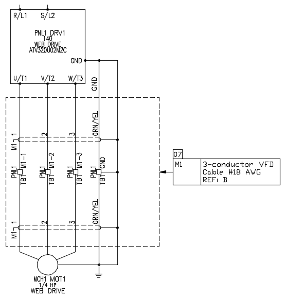
MotorPower_t8usyj.png


As can be seen on the illustration, my original plan was to land both the green/yellow ground wire and the shield at all three of the following locations:

[ol 1]
[li]At the ground terminal of the VFD (DRV1)[/li]
[li]At the ground terminal block[/li]
[li]At the ground screw in the motor’s built-in conduit box[/li]
[/ol]

When I presented this plan to the CE consultants, they told me that EMI or shield grounds should be isolated from the main safety ground. The purpose they say for this separation is that all of the noise being filtered out of the AC line by my filter is shuttled to the main safety ground plane. If I tie my shield ground to the same point electrically, that noise will likely travel on the drain wire out the the device. They say one way they have seen this addressed is with a ground bus bar mounted on isolating (thermoplastic) hardware. There is enough dead metal to dissipate the noise but is reliably separated from the main ground.

He says the termination point would be as follows:

NoiselessCleanEarthGround_kgsuif.png


I am just wondering if anyone here knows of any manufacturers that might sell hardware specifically designed for this type of noiseless / clean ground of cable shields?

Any suggestions will be greatly appreciated.

Thanks in advance,
Paul
 
Replies continue below

Recommended for you

I would just use as big of buss bar as practical. I believe the idea is to create a low impedance path, with a large surface area, to give the noise a chance to dissipate before it reaches the main ground, which could cause other issues with sensitive electronics. I haven't really checked into if this is offered as a package from a manufacturer since it really is just a big chunk of copper.
 
Don't use the ground terminal on the VFD for a ground junction point.
It is meant to be grounded, not as a point to ground other components.
Install a generic ground bus that will accommodate The largest ground conductor that will be used.
Ground everything to that bus.
Disclaimer: If jraef makes any suggestions, disregard my advice and listen to jraef.

Bill
--------------------
"Why not the best?"
Jimmy Carter
 
The diagram indicates the shield is grounded at both the source and load locations. Standard practice is to terminate at one location. This will eliminate shield ground noise.

Mike
 
Noiseless / Clean Ground for Motor Power Cable Shields
A ground installed in compliance with North American codes is usually noiseless.
The noise comes from the shield and possibly noise induced in the motor frame and carried back by the equipment grounding conductor.
When equipment is having problems with a "dirty" ground, it is often the equipment having issues that is causing the ground noise.

Bill
--------------------
"Why not the best?"
Jimmy Carter
 
Decades ago, instrumentation manufacturers specified a "clean" grounding system be provided specifically for their system and completely separate from the plant ground system. But a completely separate grounding system illegal in the US and is potentially unsafe. All grounding systems must be bonded together in at least one location. In reality, a "clean" or isolated ground is mostly mythology. We quit installing "quiet" grounds 20 years ago and somehow things keep working.
 
The instrument guys keep installing what I call the magic triangle.
In a typical tar sands installation, there will be tons of copper ground grid, and hundreds of tons of steel pilings set deep into the ground, well below the frost line.
I can't imagine what type of electrical noise would make a measurable amount of noise on that mass of grounding electrode.
Then the instrument guys drive three 10 foot ground rods in a triangle and run a conductor to the instrument ground bus.
dpc said:
All grounding systems must be bonded together in at least one location.
Yes, after the instrument guys have finished, the power guys run a 4/0 jumper from the instrument ground bus to the main ground bus to comply with the electrical code.
Of course the instrument bus is "clean".
It is connected to hundreds of tons of grounding electrodes that may extend to a depth of over 50 feet.
As for the magic triangle; these plants regularly experience minus 30 and minus 40 degrees.
Most if not all of the 10 foot ground rods will be in frozen ground.
Frozen ground is not a good conductor.
"We've always done it this way." is often too much inertia to overcome.

Bill
--------------------
"Why not the best?"
Jimmy Carter
 
Ah yes, Bill - the magic triangle. Memories! One vendor even sent us this as submittal. Fun times.
 
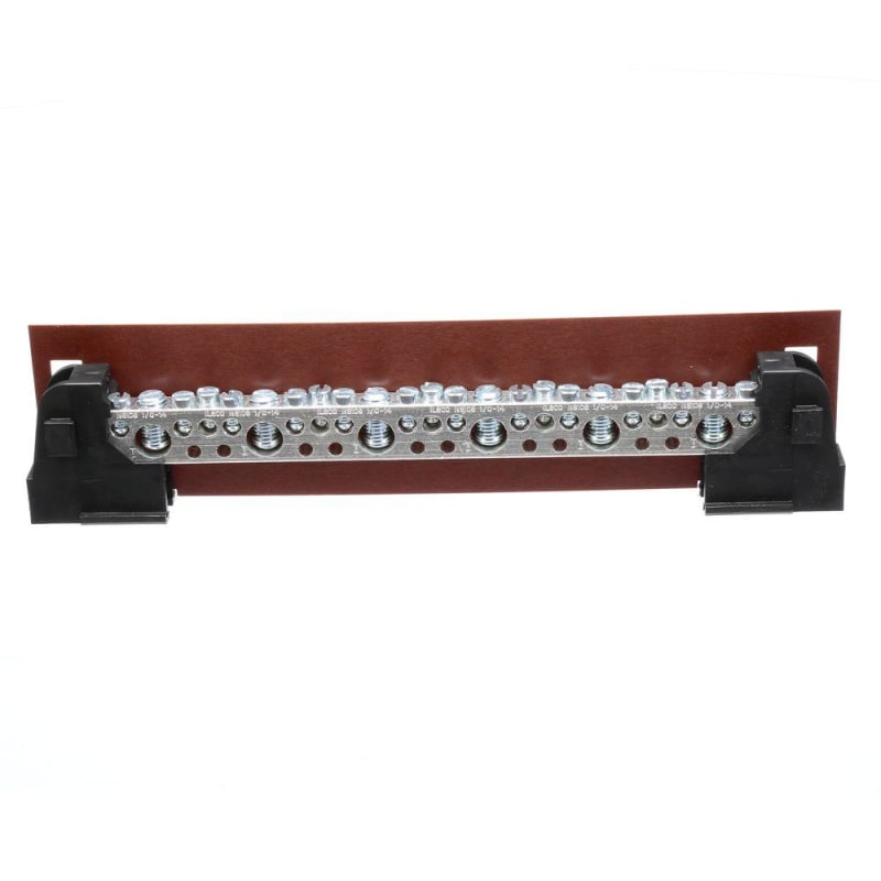
You can buy neutral kits that are various sized busbars riddled with holes and matching screws and a plastic stand that holds the busbars separate from whatever the plastic stand is mounted to.

You can get these things up to at least a foot long. Use one of them and then ground it using one of the screw/holes.

These are sold at any electrical supply place.
siemens-grounding-bars-eclx210m-64_1000_kon9aq.jpg


With a VFD you run a LARGE surface area ground from the motor directly to the big grounding screw on the VFD and nowhere else.

The large surface area is needed because the high frequency noise generated by the VFD modulation fully puts it in the skin-effect realm. The current will be traveling only near the surface of the conductor. Without a LOT of surface area the ground will present high impedance to the high frequency noise coming out of the motor and trying to return to the VFD and it will instead wander in all directions causing problems.

You then use the 'other' VFD ground terminal to connect the VFD to the safety ground in the enclosure the VFD is mounted to. This way there is no impetus for the noise out of the motor/VFD to go out to the safety ground system as it has already returned to the VFD.

Keith Cress
kcress -
 
Hello PaulKraemer
There is much fiction and theory around this subject and there are many statements by supposed experts, but the reality is somewhat different.

Most of the information that I see, is all about providing screening to prevent radiation from the output cores between the motor and the VFD. This is a very minor risk.
The major problem is not radiation from the output cables, they are too short for this. Radiation efficiency requires cable/conductor lengths approaching a quarter of a wavelength which at 150KHz (center of the noise band, is KM, not meters. The problem is conducted emmissions where the noise currents flow through the whole electrical and mechanical system and the whole structure becomes a radiator, and everything connected becomes part of the current path.
If you look at the output of the VFD, there is rapid switching PWM waveform where the output switches from the positive DC bus to the negative DC bus and back again etc. The transition time from plus to minus and minus to plus, is 10s of nS, not uS. Inside the motor, there is considerable capacitance between the stator windings and the stator frame and when this waveform is imposed on the stator windings, the parasitic capacitance is charging and discharging with the voltage transitions on the output waveform. This results in a high positive and negative charging current flowing to and from the motor frame.
The charging current, often referred to as common mode current, needs to go back to the DC bus to complete the loop. If the frame of the motor is completely isolated from all other circuits and ground paths, it will have a significant transient voltage and this voltage can cause major arcing to ground when the conditions allow. So, the effective transient source voltage at the motor frame is hundreds of volts and this will drive the charging currents via all available paths back to the DC bus. In many cases, the path includes ground to phase bypass and decoupling capacitors in other equipment, and then back to the DC bus via the input rectifier of the VFD. these currents can travel considerable distances if there is no direct path home.
IEC rated VFDs include level one EMC filters that are usually small capacitors between both legs of the DC Bus to the chassis and this is one path for the current to return.
High frequency currents in the 100KHz plus, travel on the surface of the conductor only due to skin effect and a low impedance path at these frequencies, is very much about surface area. Conductors with more than 1mm thickness do not add to the high frequency conductivity. The important issue if you are to minimise the conducted noise, is to provide a very low impedance path back to the DC bus for the whole path length between the motor frame and the VFD chassis. You can use a screened cable for this provided that there are no pigtails used and provided that the screen is continuous over the whole length. If you are going to use a terminal block for the connection inside the VFD cabinet, then you must use some form of clamp to connect to the screen without twisting it into a pigtail that will go into a terminal block. A saddle clamp around the screen (ringbark the sheath) and screwed to a metal gear tray below the terminal block with the VFD screwed to the same metal gear tray works well.
The return path can equally be via some other means than the screened cable provided that the conductor provides a large surface area relative to the surface area of the phase conductors.
The return path can be almost any conductive material, but must have at least 1mm thickness and a minimum surface area over the whole path in the order of 50 times the surface area of a phase conductor on the output of the VFD.

Best regards,

Mark Empson
Advanced Motor Control Ltd
 
Hi Mark, Keith, dpc, Bill, mparenteau, and buzzp,

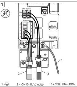
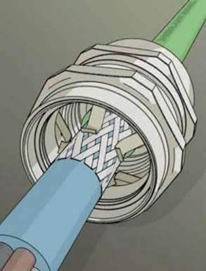
Thank you all for your thorough responses. This seems to be a complex subject that stretches the limits of my understanding. For this project, I decided I would reduce complexity and the likelihood that the consultants I have hired for assistance with CE compliance will find something they don't like in terms of EMC by giving up the idea of having terminal blocks for the cable from my VFD to my motor. After giving this further thought, it is really just as easy for me to land the cable from the motor directly at the drive terminals. Per the suggestion of the CE consultants, I am planning to strip back the insulation at each end of this VFD cable to expose its braided shield. The VFD comes with what they call an "EMC plate" that allows me to grip the braided shield with a clamp provided for this purpose. On the side of the motor, they suggest I use what they call an "EMC gland" that appears to have internal metal "fingers" that will make contact with the shield. I have pasted an illustration of both the EMC Plate and EMC gland below.

EMC-Plate_xknsju.jpg

EMC-Gland_nov4jl.jpg


I do not fully understand how this is different than "directly" landing the shield at a ground terminal (at either the motor and/or VFD), but as long as the CE consultants give me approval for this, I think I should be ok. This is a simple machine with just a 1/4 HP motor, and I have made similar machines work without issue when I paid less attention to EMC. I just need these consultants to sign off on my work, and of course, I am always interested in building the best machine possible with the most robust design.

I appreciate all your help.

Best regards,
Paul
 
It's about the skin effect. The power is flowing at the surface of the conductor, think like a halo around the conductor. If you mash the shied down flat at the ends you are reduce the surface area of the shield to the surface traveling current increasing the impedance unnecessarily. Using a metal plate on one side alleviates this clamping crunch because the current can transition to the plate's large surface area. On the motor side the 360° grips preserve the surface area connection of the current flowing off the entire motor case onto the shield. Tiz all good stuff.

That said it's overkill for 1/4hp. You could use coat hangers with spacers taped to the connections and not have a problem.

Keith Cress
kcress -
 
Dear Mr Marke

I fully agreed with your learned advice and the respected opinion: " There is much fiction and theory around this subject and there are many statements by supposed experts, but the reality is somewhat different".
With due respect, I felt that the following "over-looks" marred otherwise an excellent article;
viz.:
1) "...Radiation efficiency requires cable/conductor lengths ... at 150KHz * (center of the noise band, is KM **, not meters..."
i) The symbol "K " * is used in SI unit name kelvin, a thermodynamic temperature. In SI unit, it should be "k" , a decimal power kilo, 1000,
ii) The symbol "M" ** is used in SI unit mega, a decimal power 1000,000. In SI unit, it should be "m " an units name of length, metre.
2) "...The transition time from plus ...., is 10s of nS, not uS ... "
i) The symbol "S " is used in SI unit name siemens, a quantity of electrical conductance. In SI unit,it should be " s" , a quantity of time, second.
Che Kuan Yau (Singapore)
 
Status
Not open for further replies.

Part and Inventory Search

Sponsor