Hi all,
I'm new to the site and this is my first post.
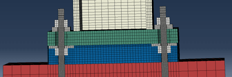
I am currently modeling a column base plate connection. All my elements are C3D8R. General contact is used. Friction property is defined between baseplate and grout as well as between anchor plates and base plate. Other surfaces are all frictionless. Tie constraints are used between column and baseplate also between grout and concrete.

I did a monotonic push (displacement control) on the column to 10% drift. The model converged and results look good comparing to experimental data.
However, when I applied a cyclic displacement to the column. The model was having convergence difficulty and the model eventually stoped at a column drift of about 0.5%. I have tried to increase the number of cutbacks and palyed around with the mesh size but the model still wouldn't work.
At the moment, I don't have any clue on what's causing the problem. Any help would be much appreciated.
I'm new to the site and this is my first post.
I am currently modeling a column base plate connection. All my elements are C3D8R. General contact is used. Friction property is defined between baseplate and grout as well as between anchor plates and base plate. Other surfaces are all frictionless. Tie constraints are used between column and baseplate also between grout and concrete.

I did a monotonic push (displacement control) on the column to 10% drift. The model converged and results look good comparing to experimental data.
However, when I applied a cyclic displacement to the column. The model was having convergence difficulty and the model eventually stoped at a column drift of about 0.5%. I have tried to increase the number of cutbacks and palyed around with the mesh size but the model still wouldn't work.
At the moment, I don't have any clue on what's causing the problem. Any help would be much appreciated.
