Continue to Site

Eng-Tips is the largest engineering community on the Internet

Intelligent Work Forums for Engineering Professionals

  • Congratulations IDS on being selected by the Eng-Tips community for having the most helpful posts in the forums last week. Way to Go!

Non destructive testing of heavy thick plates

mrmalcolm

Marine/Ocean
Jan 24, 2024
53
May I ask if colleagues have any experience in non-destructive testing of thick plates?
Where thick plates (steel plates with a thickness greater than 100mm) ,the steel mill has conducted 100% ultrasonic testing and passed it.
Then, during non-destructive testing of the weld after welding at the fabrication, discontinuities caused by steel plate defects were discovered.
Can this situation be considered as the quality of the steel not meeting the standards? How to consider this situation?
Best Regards
 
Replies continue below

Recommended for you

May I ask if colleagues have any experience in non-destructive testing of thick plates?
Where thick plates (steel plates with a thickness greater than 100mm) ,the steel mill has conducted 100% ultrasonic testing and passed it.
Then, during non-destructive testing of the weld after welding at the fabrication, discontinuities caused by steel plate defects were discovered.
Can this situation be considered as the quality of the steel not meeting the standards? How to consider this situation?
Best Regards
was this cold or hot rolled plate?
steel suppliers recommend removing stock
on the surface more for hot rolled. less for cold rolled. view on line the stock suppliers recommendation.
generally .020-.030 stock per surface
should suffice.
Blanchard surface grind is a good choice.
a large mill that can hold large material.
it has been my experience xray and ultrasonic will miss detecting surface indications. which fluorescent penetrant
will detect. or if magnetic, mag particle inspect.
ultrasonic depends on how it was calibrated.
radiographic depends on the setup.
 
Firstly check your MTR for what code and what quality grading the UT was performed to.
Just because it was 100% tested and passed does not mean it is 100% free fom discontinuities.
Quality grading will give size of allowable discontinuities.

"........discontinuities caused by steel plate defects were discovered."

This does not make sense - please explain ?
I was a level 2 NDT inspect early in my career. welded parts would pass radiographic and ultrasonic. but would fail penetrant
because it is surface defects. the other were
great at pick up subsurface defects.
if there are possible allowable sub surface
defects that will not be visible penetrant.
ultrasonic is calibrated to know samples with defect ts and I know gets complicated.
I had may parts pass ultrasonic and fail
penetrant. it is what it is
 
Thank you
For heavy thick plates, ultrasonic testing is performed in accordance with either EN 10160:1999 Level S1/E1 or ASTM A 578:2017 Level C.
For weld of the heavy thick plates, TOFD is required and the acceptance criteria is ISO 15626 level 1, or PAUT is required and the acceptance criteria is ISO 19285 level 2.
The steel plate passed the first ultrasonic testing, but during the second test of the weld(TOFD or PAUT or UT), defects (delamination, inclusions) were found that were judged to be defects in the base material.
 
It was not uncommon to repair small locations of lamination in heavy wall plate after 100% UT at the Mill. We always required MT or PT of prepared areas for welding and made repairs prior to joint welding. As an EPC company, we had a Heavy Wall Engineering specification for all vessels with a wall thickness of 4" and greater.
 
Thank you.The key is that the steel has undergone 100% non-destructive testing and meets EN 10160:1999 S1/E1 grade or ASTM A 578:2017 grade C.
However, for the steel that has already been UT qualified, defects were found in the base metal during non-destructive testing of the weld area after welding. There are two opinions:
(1) The non-destructive testing acceptance level of steel in mills(EN 10160:1999 S1/E1 grade or ASTM A 578:2017 grade C.) is lower than that of welds(ISO 11666 level 2)
(2) Different detection methods are used, with a double-crystal normal prob used for steel and angle probe used for welds.
Best Regards
In my youth I would do visual inspect of all the sheets or plate. Look for tell tale visual imperfections. If I found an area with visual imperfections, I would do a penetrant spot check. Every once in while it would glow like a Christmas tree. I seen much. Delamination , intergranual attack, (IGA), indications in general.
I would reject the entire lot. In addition I would cut out test samples for met lab micro, visual
Inspect for grain size, correct grain structure.
Machine tensile bones, for tensile testing
To strick customer requirements.
 
All NDT is a statistical game.
There will always be indications that are just below the threshold of detection.
Such that if you were to re-test to the same specification you would be highly likely to find additional indications.
At the same time you can see how there will also likely be some indications that exceed the standard that escape detection.
We used to do a demonstration where we would re-test the same material multiple times.
We would make changes in the setup but always use the same reference standard.
And there would always be differences in indication patterns.
We nearly always test a bit more sensitive than the specification required to cover these issues.
 
May or may not be relevant - see last sentence.

Through thickness properties​

Background
As mentioned previously, the properties of steel perpendicular to the plane of the element (often termed through-thickness) are different from those in plane.

The nature of the production process is such that any inclusions or discontinuities in the steel are essentially ‘rolled-out’ to be planar in extent and parallel to the surface of the plate. The result is that the mechanical properties in the through thickness direction are more susceptible to the influence of such inclusions or discontinuities.

There are two types of imperfection that affect through thickness behaviour:

  • macro imperfections - thin layers of inclusions or discontinuities, extending over an area
  • micro imperfections - numerous very small inclusions or discontinuities.

Macro imperfections are termed ‘laminations’ or ‘laminar defects’. The presence and extent of such defects can be checked by ultrasonic testing, and acceptance levels are given in EN 10160[20].

Micro imperfections are significant when the material is subject to through-thickness stress, because they can lead to ‘lamellar tearing’ as a tear propagates from one inclusion to the next. The inclusions are small, so they cannot readily be revealed by ultrasonic testing.
 
Are you performing butt welds of 100 mm plate or are you welding "Tee" joints onto the 100 mm plate ?
 
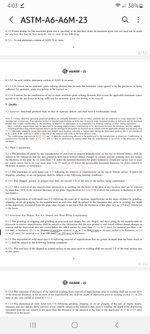
Here is an example of a typical ASTM spec
Recommended stock removal ro remove imperfections. Size needs to be adjusted
To allow for stock and to meet print thicknessScreenshot_20250410_040335_Samsung Notes.jpg
 
Many designs will consider both yield strength and tensile strength.
Yield strength and tensile strength of base material need to be separately measured and satisfied for the design.
As an example, the test result is a yield strength of 270 MPa for the base material and a tensile strength of 300 MPa for the base material.
Tensile testing of welded joints is required. Since welded joints are not homogeneous joints, only the tensile strength is measured. The tensile test result of the welded joint is a tensile strength of 310 MPa, which is not lower than the minimum tensile strength value 300 MPa specified for the base metal.
How to determine the ‘yield strength’ of a welded joint is not less than the yield strength of the base material of 270Mpa, which is the yield strength required by design.
Thank you.
 

Part and Inventory Search

Sponsor