Continue to Site

Eng-Tips is the largest engineering community on the Internet

Intelligent Work Forums for Engineering Professionals

  • Congratulations IDS on being selected by the Eng-Tips community for having the most helpful posts in the forums last week. Way to Go!

Noryl Impeller in high pressure pump failure

Status
Not open for further replies.

dbill74

Mechanical
Feb 26, 2009
538
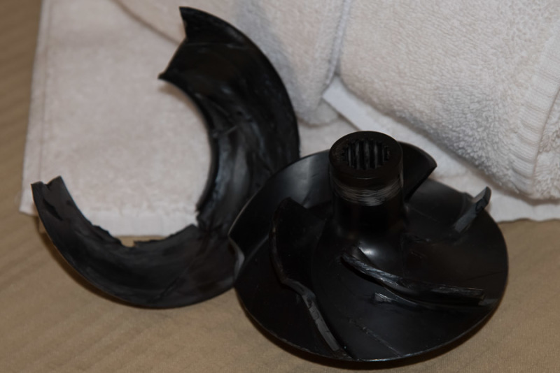
Currently in the midst of an investigation into the failure of a high pressure booster pump. Today I was finally able to eyes on broken impellers. The pump is scheduled to deliver filtered sea water into RO membranes pressure vessels.

Pump details:
Energy Recovery Inc.
Model: HP-2403
3 stage centrifugal
300 GPM @50 psi
Boosting from 700 psi to 750 psi.
20 HP

We have had multiple failures in 4 pumps. Failures are occuring 2-3 weeks after startup.

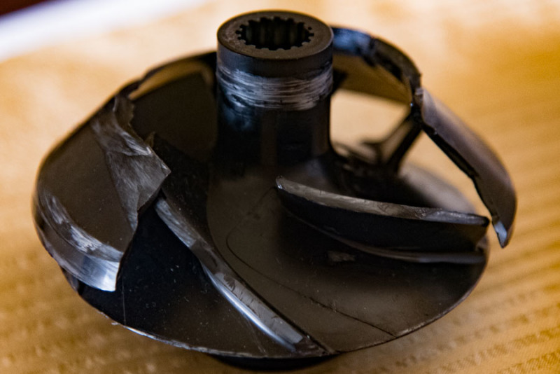
Markings on the destroyed impellers along with testimony that VFDs are ramping up speed or hunting within hours of failure lead me to believe failure is due to contact between the impellers and housing. Tomorrow we are going to investigate further why this contact is occuring.

Now to the thread title and reason for this thread; per pump specification and submittal data the impellers are made of Noryl. Googling Noryl, I find evidence that this material can "absorb" water. Is this right? When used for a pump's impeller, does material expansion need to be considered as a possibility in these failures?

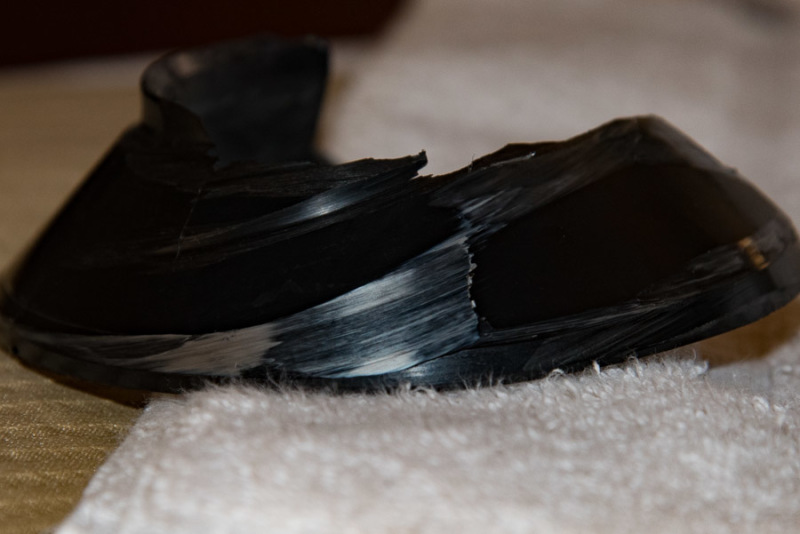
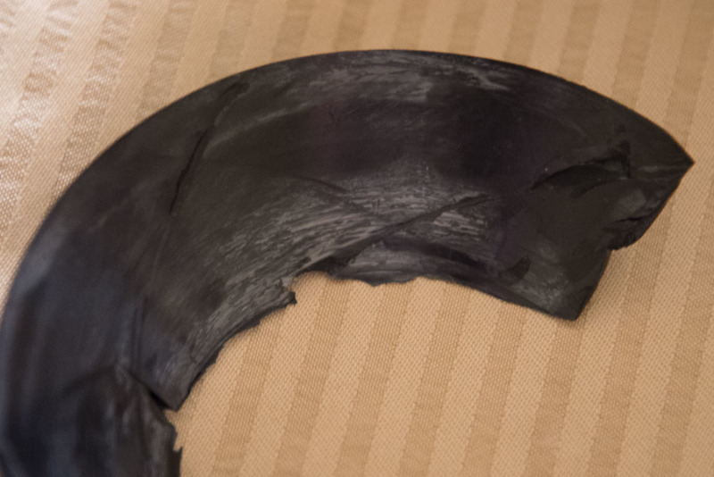
I've also notice white discoloration. I'm not completely convinced the discoloration is due to rubbing or a result of chemical interaction. What, if any chemicals can have an impact on the properties of Noryl plastic? Or just cause some discoloration?

Gonna keep searching Google results, there is just so much information out there finding what I am looking for is like finding a needle in a hay stack. If someone here can help me narrow my search, I would appreciate it.

Attached photos are of multiple failed impellers, when more than one piece is in a photo, there is no guarntee or promise that the pieces are from the same impeller.
20170718-pump_impeller-001_v4zjq7.jpg

20170718-pump_impeller-002_e0ja7c.jpg
20170718-pump_impeller-003_lelzm5.jpg
20170718-pump_impeller-004_fis4rg.jpg
20170718-pump_impeller-005_lnxa71.jpg
 
Replies continue below

Recommended for you

Think Noryl can be actually an alternative to impeller´s materials such as Bronze (cheap but not well suited for the presence of Ammonia), Carbon steel or even Stainless steel (when prone to corrosion). I know Noryl is originally patented by GE. As long as the selection is within manufacturer experience envelop with respect to peripheral speed, service pressure among other things and it is compatible with the fluid (filtered sea water does not look aggressive for Noryl, but I may be wrong), there should be no problem. The thing I definitely cannot comment is the service and pressure of 750 PSI. I am completely ignorant in that respect. Have been selecting Noryl for borehole submersible pump as alternative to duplex SS in presence of warm and corrosive water plus presence of Ammonia. Never selected this material in high pressure pump feeding RO unit. As a completely side note and even not sure if it is relevant or not, for relatively big RO installation (city size desalination plant), the feeding pumps are generally crucial enough to the facility that it is selected to the state of the art (i.e. which often means also that it would not be the cheapest).

 
Thanks for the reply rotw.

Talking more with the plant operator, I'm steering away from a materials problem. The operator in a desperate attempt to get these working for more than a couple weeks has been using spare parts they have for older pumps that are scheduled for demolition once these are running right. Same size and model pump on the old trains. But the old trains are not failing and the only reason site is not running out of water.

I'm wondering if cavitation is at play here. Need to take a closer look at the differences between the old and new trains.

 
By the way, looking at the duty, you seem to have a combination of high head and relatively low flow.
Not sure about the RPM but it seems that the specific speed is quite on the lower range. So I was just wondering if this is not a sort of borderline selection which has been pushed to improve efficiency?
Looking visually at the geometry and shape of the impeller per the pictures, the geometry looks pretty much leaning towards higher range of peripheral speed (more of a 3D /mixed flow profile). The end result could be a design operating in uncharted experience area.

Take this with grain of salt...very speculative, hopefully just to trigger some thinking around the issue...


Is there wear on the inlet end of all of the impellers?
Is this a clearance or thrust issue maybe?
It looks like the shroud was rubbing.
Plastic impellers expand a lot more than metal does, so clearances need to be adjusted accordingly.

= = = = = = = = = = = = = = = = = = = =
P.E. Metallurgy, Plymouth Tube
 
Plastic impellers expand a lot more than metal does, so clearances need to be adjusted accordingly.

Can you elaborate more on what clearances are meant to be adjusted? thinking is that at commissioning/start-up the pump is already assembled and tested and there is no opportunity to adjust any of the internals, nor should there be some operation or sequence to be dealt with by the user in this respect unless of course you mean something different. I suppose the adjustments are the ones that pertain to the installation on foundation or alike. I suppose that the clearances of any of the internals which are to accommodate the higher tendency of the material to expand in thus particular case would need to be accounted for in the design and subsequently during the assembly procedure at the shop. Not even sure if this is a pre-engineered type of product or include some tailor made design.

I am really not an expert, I am just probing the subject in order to learn more about this issue. Thanks for your input.

 
EdStainless said:
Is there wear on the inlet end of all of the impellers?
Within an individual pump, no. This and the manner in which the impellers are broken are lead me to a single conclusion of "how" they are failing. Another observation I have made is that the top "cover" of the impeller is welded onto the blades and is a weak point in the impeller. Thus my conclusion for how they are failing is this: the outer ring of the inlet of the impeller is binding and is then torqued/twisted off the blades. With the shaft and blade turning at 3750 rpm (I need to double check this for you) and now a loose piece in there, it just tears itself apart.

Is this a clearance or thrust issue maybe?
I've been contemplating this question myself. I have not been able to rule these issues out as the cause yet.
If it is a thrust issue I would expect to see more damage on the top of the cover plate. At least more consistent circular scarring. The marks I have seen look to be more from post failure while the cover is banging around inside the housing from contact with the blades.

Some more pictures:
20170719-pump_impeller-006_izj1p7.jpg

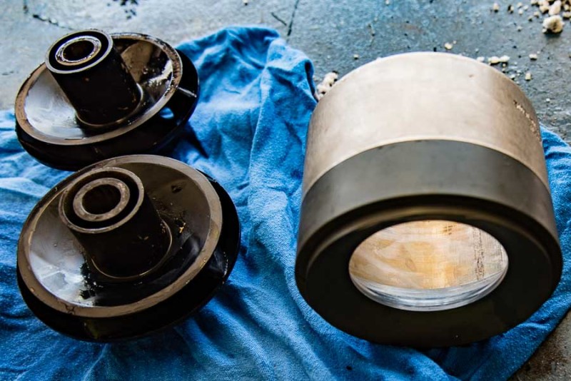
Intact impellers and housing at first stage. Impellers fit in the housing from the top of the photo and water inlet is from the bottom. Grey cover plate on end is PVC per submittal sheet. Tubular shroud is metal.

20170719-pump_impeller-007_geb3fa.jpg

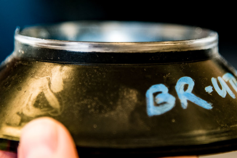
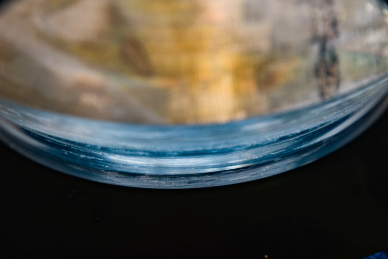
Closeup of PVC first stage housing cap. Photo edited to enhance marring resulting in the PVC looking black, in reality it is grey.

20170719-pump_impeller-010_skivn5.jpg

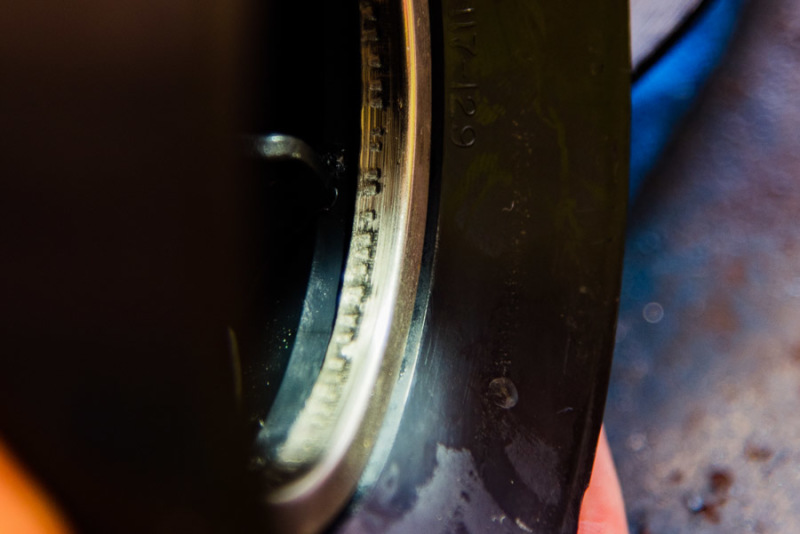
Close up of 2nd or 3rd stage housing showing evidence of contact with the impeller. Outer ring of impeller cap fits inside metal ring of this housing piece. This housing piece contain guide vanes directing water from previous stage into inlet of the next stage; except for the metal ring (crimped on), the piece is Noryl plastic, same as the impellers.

20170719-pump_impeller-008_kkby0a.jpg

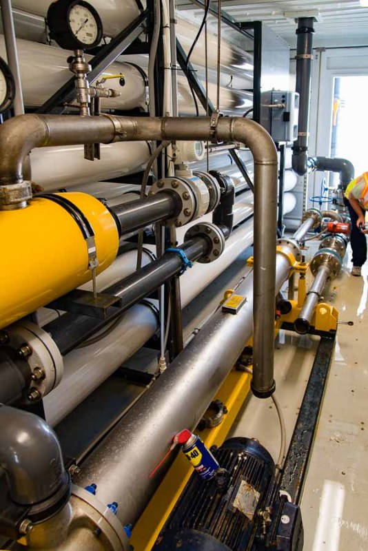
View of the RO membranes and piping. Booster pump that is failing is at the very bottom (WD-40 can is on the motor), impeller section has been removed for inspection. WD-40 can is leaning against the impeller section of the primary high pressure pump (motor is just of photo to left). Yellow device on left is the energy recovery device (Pressure Exchanger). Feed flows into the end of the recovery device, then out the top and down to booster pump.

20170719-pump_impeller-009_vfemhw.jpg

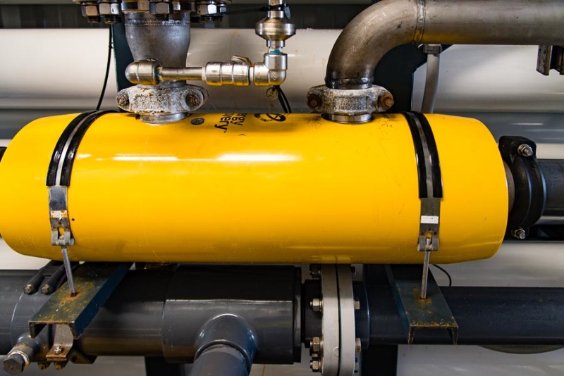
The Energy recovery device/pressure exchanger. There are 2 flows through this device, on the right is the feed water, goes in on the end, out the top at ~750 psi. As you can see in the previous image, there are no gauges to validate pressure or flow between the recovery device and the booster pump. On the left side of the recovery device is the concentrate flow; water from the membranes that is not processed comes in on the top left, and exits out the left end.
 
We have about 16 of these pumps in RO service. We have experienced many failures where the plastic impellers break up. We have tried resolving issues related to cavitation, pipe strain and start-up procedures. We continue to have failures. We are in the process of converting to stainless steel impellers. I believe the main issue with our pumps is related to start-up and shut-down resulting in periods of operation at very low or very high flow.


Johnny Pellin
 
 http://files.engineering.com/getfile.aspx?folder=63b907c3-0fbc-419c-a9a5-277e9fb699b8&file=Flint_1.jpg
My experience with closed plastic stages was with Ryton PPS.
We worked hard on the welding of the shrouds.
And yes, these designs are less tolerant of high flow/low flow than metal impellers.
1. they are more temperature sensitive
2. not as stiff
We used trust washers that were inserted so that in up thrust we didn't run directly on the impeller shroud.

My temp comment is related to the high thermal expansion, and that clearances need to be designed for the operating temp, not room temp.

= = = = = = = = = = = = = = = = = = = =
P.E. Metallurgy, Plymouth Tube
 
Glad to know that my facility is not the only one that has experienced these failuers. At the same time, it is disappointing that manufactureres are using cheap parts.

I understand what you are saying there Ed. Thermal expansion is currently in consideration as a contributing factor to the failures.
 
Status
Not open for further replies.

Part and Inventory Search

Sponsor