Eng-Tips is the largest engineering community on the Internet

Intelligent Work Forums for Engineering Professionals

Not Seeing Engine Orders in Vibration Frequency Spectrum???

Status
Not open for further replies.

TylerJ0

Mechanical
Nov 19, 2015
12
0
0
US
Hello all,

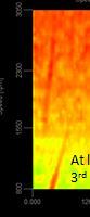
I'm working on recording some vibration data for an engine block and the data has me a little confused. I've got 3 triaxial accelerometers installed at various locations on the engine block (front side, rear side, front face) as well as one installed on an EPR valve mounted on the engine. The problem is that when I perform a speed sweep on the engine all the block accels don't show any clear engine orders? The EPR accel looks great, I see 1st order, 3rd order, a bunch of harmonics, just like I would expect but none of the block ones show much of anything...in fact the frequency spectrum looks like it's just random noise. It's like the engine orders are hidden in the noise, but I'm not sure how that would be possible...I've worked with this type of stuff before and have never had any issue acquiring block vibrations...I even switched accels to see if it was instrumentation and the EPR always looked good and the block always looked bad. There's something I'm just not getting here.

The time data shows what looks like "ticks" occuring periodically that are high in acceleration but short in length (in fact they look to be pegging out my 50G accelerometers). So I'm wondering if that's the problem, but if that's the case then that means the signal is representing something real and that's even more confusing. Any and all help is appreciated Thanks!

Tyler

PS I threw some screenshots of the plots into a powerpoint and attached it to the post for reference.
 
 http://files.engineering.com/getfile.aspx?folder=9198cd8b-829b-42a2-8003-fe15403ddff2&file=block_vs_epr_vibration.pptx
Replies continue below

Recommended for you

Can you describe the engine properly? For instance, an I6 is reasonably balanced in many ways, and so shows very little order related stuff that is not a function of IMEP, whereas your usual I4 bangs out 20g of 2nd order whatever the throttle opening.

However

etips_izvn8x.jpg


is just plain wrong

Cheers

Greg Locock


New here? Try reading these, they might help FAQ731-376
 
The engine is a V6...in the past I've exclusively worked with inline 6 engines which is why this stood out so much.

I was thinking it could be electronic interference, since it is a spark ignited engine (my past experience was diesel) but with 4 accels I should get varying degrees of noise based off location I would think? Not 3 that just barely work and 1 that works fine. The wire routing is all very similiar, even for the accel that's putting out good data.

Tyler
 
TylerJ0,

I'm guessing the EPR is 'isolated' from the engine at the attachment such that it acts like a mechanical low pass filter. If it was electrical noise, you would have seen it in the EPR as well. The 'ticks' doesn't appear to be periodic.

Is the engine hard mounted to the fixture/stand?


Best regards,
Jason
 
Would a ground loop issue cause this? The block is grounded to the engine battery while the DAQ is grounded to earth through the wall outlet? I thought ground loops would give a 60hz noise spike but maybe it can throw a bunch of white noise in the signal too? I could see a gasket or something isolating the EPR signal. I'm grasping at straws here...

Tyler
 
Tyler,

Is the mounting to the dyno also soft?
Any chance you have a laser vibrometer handy?

In a bind, I've seen in the past testers glue a very thin/hard rubber strip between the accelerometer and engine to remove the very high frequency mechanical noise. Best to first confirm the transfer function on a shaker is as expected.


Best regards,
Jason
 
It looks like accelerometer overload at above 50 G's. What is the accelerometer rated for? Did you use a stud mount or a magnet base that can be overloaded? Did you exceed the temperature limit of the accelerometer?

Walt
 
Yeah it is getting overloaded a bit, but we're starting to lean towards this being a ground loop that's causing interference on all the accels that are installed on the engine block. The overloads are all due to the pulses with are very short in duration...it's not creating a flat point in the signal, it actually looks like it only effects a single point in a pulse... so I wouldn't think the frequency response would be effected too much.

It's an adhesive mount so there's no extra isolation between the block and accels (as well as the other accels mounted to the block).

We're looking into isolating bases to see if that helps.

Tyler
 
Velocity instead of acceleration would be better to see the low frequency engine orders, especially with the 3D plot that does not have much visual dynamic range.

Walt
 
Tyler,

I am skeptical the cause is ground loop. Reasons are:[ul][li]No strange noise problems below ~1000RPM. Ground loop is a persistent phenomena.[/li]
[li]No strange noise at EPR (unless this is isolated somehow)[/li]
[/ul]

I'm speculating the accelerometers are 'feeling' large accelerations at high frequency. I could be wrong but you could verify this quickly by acquiring at your highest sampling rate at 1800RPM steady state. Your data will still be clipped but the rate of which it gets clipped may be informative.


Best regards,
Jason
 
If you are using ICP-type accelerometers, then the maximum acceleration level is dependent upon not only the rated value for the accelerometer but the DC power supply voltage. If the ICP supply voltage from your DAQ system is lower than the accelerometer rated voltage, then clipping will occur at lower G values. I agree with Jason that you do not have a ground loop problem. I would try a less sensitive single axis accelerometer; such as 10 mV per G that is rated for the surface temperature.

Walt
 
The accels rated max temp is 225F, and engine coolant temp is around 180F...I don't have thermocouple data for block surface temps but I have to imagine it's near the coolant temps.

The supply to the sensors is a current range of 2-20mA and my DAQ is setup to supply 8mA.

Sidenote, I've tested the same engine in the past with the same accelerometers and a different daq system and didn't see this issue. Which is another reason we're thinking there's something electrical going on. The first test was with a PCB amplifier and an NI cDAQ, this test was with a Dewesoft DAQ slice. Not sure if anyone has any experience with Dewesoft that may shed some light here.

Not to keep harping on the ground loop theory but, the noise issue is there are lower rpms, it's just not as strong...with good data I can pick nearly ever half engine order regardless of RPM, this time, at low rpms, we could only (barely) see 1st and 3rd (firing) order. The plots in my original post are on a log scale so the orders will pop more.

Tyler

 
"The supply to the sensors is a current range of 2-20mA and my DAQ is setup to supply 8mA."

It is not so much about the current as it is the DC voltage. The AC voltage swing (+/-) must be less than the DC supply voltage (headroom). Check the voltage of the PCB amplifier and compare to the DAQ in use now.

Walt
 
I thought it just looked like clipping (unless your time-domain plot has a zoomed y-axis). That would mess up your spectrum.

What does the signal sound like? Ears are much better than DSP/spectral analysis for spotting measurement issues. If it stops sounding like an engine, something's up. Basic rule of thumb: Always listen to your signals before you believe them.

Steve
 
Status
Not open for further replies.
Back
Top