Continue to Site

Eng-Tips is the largest engineering community on the Internet

Intelligent Work Forums for Engineering Professionals

  • Congratulations KootK on being selected by the Eng-Tips community for having the most helpful posts in the forums last week. Way to Go!

Not sure how to address forces from one beam to another

Status
Not open for further replies.

bojoka4052

Mechanical
Oct 8, 2021
108
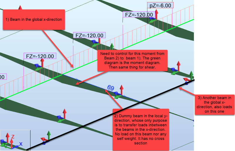
I have beam 1) for which I have checked the loads. Ive been told I need to control for the moment and shear from beam 2) onto beam 1) aswell. I dont understand how this works, how does the shear and moment from beam 2) affect beam 1)?

1_vicvqg.jpg


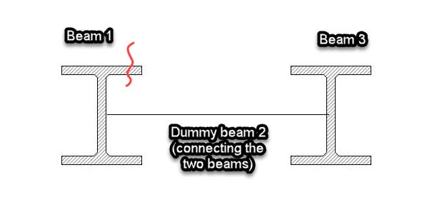
This is how the beams 1 and 3 look, they're supposed to be RC beams. I believe they were interested in the red line on "top plate" for beam 1), and if it can bear the loads it already has in addition to the moment and shear transferred to it from beam 2).

2_dzc4my.jpg
 
Replies continue below

Recommended for you

it looks like these beams are uniformly loaded ... the loads on beam1 are the same (or similar to) the loads on the adjacent beam. So I don't know what you can do to "control" the moment from the adjacent beam. Possibly the comment meant "lateral stability" of the beams ?

but then I think RC means Radio Controlled (yes, I know it means Reinforced Concrete) so what do I know ??

"Hoffen wir mal, dass alles gut geht !"
General Paulus, Nov 1942, outside Stalingrad after the launch of Operation Uranus.
 
If they're just there to brace the beams laterally, release moments and shears at the ends of the #2 beams and have them as axially loaded members only. To avoid the potential issue about self weight and no shear connection, just make the density of your dummy beams zero.
 
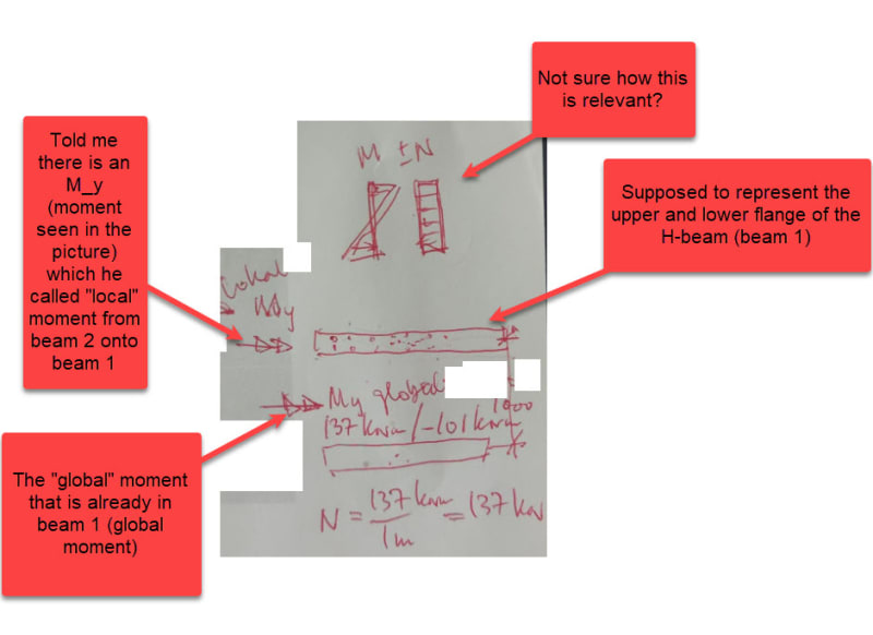
These are the notes my colleague made for me; does it make any more sense?
1_synt5n.jpg


The dummy beams are there to distribute the loads inbetween the "real beams". What I am trying to do is Grillage Analysis of Bridge Decks, which is why I have this setup with dummy elements.
 
"M +-N" ... shows (I think) that bending stresses combine with axial (tension of compression).

Ok, AIUI beam 2 is lateral to beam 1. Beam 1 is the primary load bearing member and beam 2 is a lateral support to beam 1. yes?
Or is beam 2 a tributary, carrying load into beam 1 ? (and stabilising beam 1 laterally as well)

"My" ... is this drawn consistently ? My can be the primary bending of beam 1, but then it isn't the bending moment in beam 2.
I'm assuming your co-ordinate systems is x- along beam 1, y- lateral to beam 1 (so primary bending of beam 1), and z- up.
Then Y- is axial to beam 2 and bending in beam 2 is Mx.
It's important to be precise when this is all we have to go by.

If there is a uniform load on the plate (floor ?) supported by beam 1 and 2 (and others) then ...
1) is the load being reacted by beam 1 (and his parallel neighbours) ? or
2) is beam 2 reacting some of the applied load, and "dumping" this load into beam 1 ? or
3) you're looking at "overlapping assumptions" ... yes, the critical loading is taken by beam 1 (1) but you want to consider the loading on beam 2 so that you can show that this loadpath isn't expected to fail (even if you can show that the failure of beam 2 doesn't impact the load capability of the structure (there's enough strength in beam 1 to carry the load) ??

"Hoffen wir mal, dass alles gut geht !"
General Paulus, Nov 1942, outside Stalingrad after the launch of Operation Uranus.
 
A cross section through the actual structure would be useful.

If you are not familiar with grillage analysis of bridge decks I would recommend "Bridge Deck Behaviour" by Hambly. It is pretty old now, but it covers the basics well.

I think it is misleading to call the transverse members "dummy beams". They represent whatever is connecting the longitudinal beams, which I am guessing is just the top slab.

For the longitudinal actions in the main beams you don't need to adjust the computer output; it already includes any transfer of loads between the beams.

For the transverse design of the top slab the computer output will give you the global moments and shears, due to differential deflection of the main beams. You will have to add to that the local effects of wheel loads not directly above the longitudinal beam webs.

Doug Jenkins
Interactive Design Services
 
Assuming this is the same bridge superstructure from your other thread, I think your client and your firm would be better served, both in design time and efficiency of the result, to hand this off to a design consultant with experience in bridge design. Designing bridges is specialized branch of structural engineering that has a steep learning curve, and this one would push the limits of my abilities, and designing bridges has been the bulk of my work for 20 years.

Rod Smith, P.E., The artist formerly known as HotRod10
 
IDS said:
You will have to add to that the local effects of wheel loads not directly above the longitudinal beam webs.
Could you please elaborate on this?

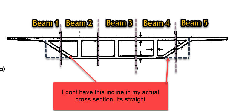
This is similar to how my cross section looks; there are 5 different logitudinal beams on which I have applied all the loads. The transverse or what I earlier called "dummy elements" are connecting them, they have no self weight. My computer model includes all the loads there are on the longitudinal beam, but I struggle to understand what transverse effect I need to think of?
1_ukxtip.jpg
 
You are attempting to design a concrete (presumably also post-tensioned) box girder with multiple boxes connected to triangularly shaped edges with an outstand slab to top it off. The model you are using for this - apparently a model of only the box girder webs, and with some sort of "dummy beams" representing the flanges of the boxes - is completely wrong. The load transfer between boxes cannot be represented by a "dummy beam" which transfers load into the webs from each tributary width. The transverse effect you struggle to think of is the fact that boxes do not behave identically to T-beams in a row, and even in T-beams or I-beams, torsion due to transverse eccentricity of load w.r.t. girder centroids is a mechanics problem which can be solved by e.g., influence lines or suitable computer models.

I recommend you to let your more experienced colleagues handle this design, or to change the design completely to a row of T-beams, since that design is easier and also more efficient if the bridge is straight and only minor amounts of torsion in girders is expected.
 
I don't recall which country you are from, but in our area engineering ethics requires we ask ourselves if we believe we are qualified for work we undertake. I studied this type of bridge in University, but not under an experienced engineer, so I would not undertake a project like this. If you do not have a mentor experienced in this type of bridge design I think you need to retain an expert. This is not meant to be rude, but this step is tripping you up, and this represents a very small part of the design.
 
centondollar said:
...a model of only the box girder webs, and with some sort of "dummy beams" representing the flanges of the boxes - is completely wrong. The load transfer between boxes cannot be represented by a "dummy beam" which transfers load into the webs from each tributary width.

Yes, the bottom and top flanges are not "dummy beams". They make the superstructure transversely very rigid. You'll get nearly complete moment and shear transfer. At the very least, it should be modeled with full continuous moment connection between the beams. To most accurately capture the actual behavior, it should be modeled as a single rigid cross section.

Your questions and modeling of this indicates you are well outside of your area of expertise. I again implore you to let someone with experience in bridge design take the lead, so that you can watch and learn.

Rod Smith, P.E., The artist formerly known as HotRod10
 
do you mean we can't learn bridge design from a couple posts on the internet, being answered by who knows who ?

The OP has a colleague he's (presumably) working with ... maybe this is the guy you should say "man, I don't follow what you mean".

"Hoffen wir mal, dass alles gut geht !"
General Paulus, Nov 1942, outside Stalingrad after the launch of Operation Uranus.
 
Bojoka4052:
You claim to have modeled your structure correctly in your software, you claim to have included all the correct loadings in your model and then you model a continuous perpendicular spanning load distributing element (the deck slab) as discrete beam elements, at some spacing. All the while seeming to have no understanding or engineering knowledge of how this structure really works in the real world. You show a weird-assed moment diagram in the conc. slab/discrete, non-existent cross beam, no dimensions, no loads, no nothin, just some imaginary moments, and you show what appears to be a couple WF steel beams, with a string (or something) btwn. them, all absolutely contrary to the real world conditions. I think your model and your assumptions need some serious review and scrutiny. And, finally, like the effort involved in pulling teeth, seven or eight post later, you show a cross section of a bridge section which an experienced Structural Engineer would actually recognize and understand. So, the prior six or seven posts, all by knowledgeable and experienced Etips members were just guessing at what you had, and kinda a waste of their time, all for your lack of defining your problem properly/adequately, in the first place. Don’t use us/ETips as a crutch for your lack of real world engineering knowledge. You have to define your problem with enough meaningful engineering info., sketches and the like, so an experienced engineer understands what you are trying to do, or you are wasting everyone’s time.

Take this problem back to your boss, and work it out, so he knows what you know and what you don’t know, so he can guide you accordingly, and keep you and the company out of serious trouble. I think what he is saying is that you have significant bending normal stresses, or shears, in the X & the Y directions in the slab, due to bending in the primary beam members and in the slab bending across the main beams respetively, and you should pay some attention to those combined stresses in the slab.
 
bojoka4052:

If your beam looks anything like the cross section that I have drawn below in yellow you model is completely wrong.

Box_Beam_u9bwj7.png


As said in some posts already, you have a box girder that supports the load with a combination of bending shear and torsion. I think that the shear center is somewhere close to the vertical wall below your label "Beam 3". Load from a vehicle on "Beam 3" will not cause any significant torsion on the beam while load on Beam 1 or 5 will maximize it. As please note, you don't have five beams, you have only one.

Based on your questions on this subject, you need more help that an Internet forum can provide.

Thomas
 
Status
Not open for further replies.

Part and Inventory Search

Sponsor