Continue to Site

Eng-Tips is the largest engineering community on the Internet

Intelligent Work Forums for Engineering Professionals

  • Congratulations waross on being selected by the Eng-Tips community for having the most helpful posts in the forums last week. Way to Go!

Nozzle to Shell Weld

IdanPV

Mechanical
Aug 26, 2019
473
Hello all,

I have a question regarding a nozzle to shell welding in an ASME "U" vessel.
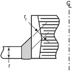
The weld detail is similar to that shown in ASME VIII-2 Table 4.2.12 detail 3/ASME VIII-1 Figure UW-16.1(z-1) except that there is no bevel in the shell, and the shell is completely straight.
See illustration below (ignore the "tc" marking please)
1738501323979.png
1. Is this kind of weld detail is acceptable?
2. What would be the correct symbol for this weld as per AWS and ISO.

Thanks,
 
Last edited:
Replies continue below

Recommended for you

Hi,
1. in edition 2023 of code i see a different detail. Note that figures UW-16 are "some acceptable...", not mandatory. Even if i never seen square groove weld, in particular in shell to nozzle joint, any detail as long as it is qualified with a dedicated PQR should be acceptable.
2. google "square groove weld".
 
Thank you @pvros.

1. Edtion 2023 do contain differnet "acceptable" details, with bevel, and I am looking for a square groove as you said.
2. Note that this is a combination of groove and fillet, and I did search for "combination groove and fillet weld symbol" and also looked in AWS A2.4.
I was only able to find "bevel-groove and fillet weld symbol".
The only thing which seems to be acceptable for my case is AWS A2.4, Figure 6.3 (D), however, it's not realy my case.
 
I agree that you may use 6.3(d), just drafting half of the symbol.

I'm a bit perplex you are using an "uncommon" weld detail that you even did not know how to indicate, but again, if you are able to qualify it...
 
I understand where this comes from.
Typically, we use a fillet weld from the outside only, as permitted by UW-16(f)(3).

However, due to manufacturing constraints, we now need to modify this approach.

Adding a chamfer or creating an angle in the shell to fully comply with Figure UW-16.1(c), (d), or (z-1) increases production costs and adds some complexity to the process.
 
Don't know what the thickness of those parts is, but you are essentially doing a weld buildup with that configuration.
 
Shell - 5mm
Nozzle - varies from 4 to 5.5mm

Question is does it mandatory to create a chamfer in the shell or it is permitted to leave it straight.
 
Last edited:
Question is does in mandatory to create a chamfer in the shell or it is permitted to leave it straight.
What is the gap between the shell and nozzle? Does the gap meet the requirement for the welding process you are using? How are you going to fit-up the nozzle? Are you meeting are the parameters in your WPS/PQR?
 
Thanks @Trestala, I will try to share some more information:
1. The gap between the shell and nozzle is about 2mm.
2. The WPS I want to use doesn't fit exactly because it includes a chamfer in one of the parts, however, as per ASME IX, Table QW-255, changing the Groove design for GMAW welding is define as nonessential variable.
3. Fit-up the nozzle will be made using tack welds (UW-31(c))
 

Part and Inventory Search

Sponsor