Continue to Site

Eng-Tips is the largest engineering community on the Internet

Intelligent Work Forums for Engineering Professionals

  • Congratulations IDS on being selected by the Eng-Tips community for having the most helpful posts in the forums last week. Way to Go!

Nozzle verification EN code

Status
Not open for further replies.

Ehiman1

Civil/Environmental
Oct 17, 2014
59
Hello,
I have a huge nozzle 80” diameter on a vessel 120” diameter that I calculated with EN 13445.
The verification involves the reinforced area of the opening only against internal pressure.
In order to satisfy the verification I used a reinforcing Pad 95” diameter (all components have the same thickness 1”) and the check is ok ecxept for the size limitation that is outside d/2ri < 0.5 (it is 0.7).
Because of these reasons I included a verification with other codes Such as:
ASME Viii div1 app 46 and everything is ok and a Fea with EN code.

Regarding this last point I noticed that with Tresca the verification fails 103%, but with Von Mises it is ok (92%).
Actually I don’t understand Why the results are so different, could someone please help me?

EN code is more restrictive than ASME because Pb is considered as primary stress (with ASME code I am at 60% against 92/103 of the EN code)
 
Replies continue below

Recommended for you

Isn't bending stresses due to internal pressure secondary for the EU code? There is even an option to make the bending stresses dues to applied loads secondary.
Placing a Re-Pad on such a large d/D ratio sounds like a bodge to me. FEM can't model that accurately.
I would make the cylinder thicker at the location of the nozzle. Will likely be the less expensive option as well.
 
Ehiman1
What are you looking for? Do you think this is a game?.

Regards
 
DriveMeNuts, Why would FEM not model this accurately?

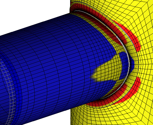
Screenshot_2021-07-05_123033_tnyjh7.gif
 
KevinNZ,
I have a couple of concerns.

I question whether the stresses adjacent to the nozzle are considered "Primary Local membrane Stress". As the nozzle is so large, perhaps the stress is better described as a General or Global Membrane stress.
I'm referring to Section 5.2.1.2 and 5.2.2.2(b)(1) of ASME VIII Div 2. I suppose this stress re-classification can be checked and done if required.

I also question the accuracy of modelling the contact between Re-Pad and Shell. Does the FEM model include contact constraints between the two. For a smaller nozzle this issue also exists, however because of the small geometric size the effect on accuracy is smaller and therefore through industry experience this is considered acceptable.
 
Seems like your concerns are with stress classification, which is part of post processing, it has nothing to do with the accuracy or suitability of linear FEA. Nonlinear FEA is also accurate and eliminates the need for stress classification. Some of the membrane stresses are secondary, so if you class them all as primary this would be acceptable, and is still conservative relative to non-linear methods. The general membrane limit is not applicable at a gross structural discontinuity. If contact is included or not depends on how the model is configured by the user, whether it is necessary or not comes down to the specific application and engineering judgement / experience.
 
BJI,
Stress classification is part of all steps of the design. Probably the most important to prevent wasting time is the step before pre-processing where the engineer uses experience and judgement to decide if the geometry can use the linear stress classification method. Section 5.2.1.2.

You are right about the general membrane limit not being applicable at a gross structural discontinuity. My point was that if the primary membrane stress exceeds 1.1S for a distance of SQRT(Rt) away from the Gross structural discontinuity then the stress is not Primary local membrane and can't be classified at all. A change in geometry/thickness to pass the check or an elastic-plastic analysis would be required.
As small nozzles tend not to fail this test, the focus is on assessing Primary local membrane stress immediately next to the junction to prevent excessive plastic deformation.
For larger T-Junctions, the broader general stresses become a consideration to prevent the general collapse of the cylinder, hence the reason for the 1.1S check. The Div 2 rules say that if the check can be passed, then the primary local stress at the junction needs to also be assessed.
Div 1 Appendix 1-7 (large nozzles) doesn't bother with checking the local membrane stress at the junction and instead focuses on setting the limit of the average membrane stress in the region away from the Gross structural discontinuity to Sm < S. Perhaps this method conservative enough to automatically pass the PL < 1.5S test.

Re-Pads were adapted to be used in pressure vessels from shipbuilding a century ago. They were developed through practical experience. The contact region and weld between pad and shell is different for every nozzle, therefore it is not possible to accurately model Re-Pad nozzles using FEM. The best that can be achieved is "a good enough bodge". The bigger the d/D and wider the pad, the bigger the bodge. Modelling the shell and Re-Pad as a single piece of material like the image above appears is an even bigger bodge. How large and wide does the nozzle and pad need to go before the boundary of industry experience has been exceeded and you are naively (and recklessly) winging it into the unknown?
 
Did any of you think if the pad is allowed for this example?
Did any of you think about what non-destructive tests should be done?

Regards
 
Status
Not open for further replies.

Part and Inventory Search

Sponsor