Eng-Tips is the largest engineering community on the Internet

Intelligent Work Forums for Engineering Professionals

NPSH margin in centrifugal pump 7

Status
Not open for further replies.

maatoug

Mechanical
Feb 5, 2020
14
0
0
DZ
hello hope you are doing well
about the margin between NPSH disponible and NPSH required in centrifugal pump ,
with
design pressure 11 barg
design temperature 90
RPM 1200
process fluid water with traces of co2 and condensate
discharge pressure 4 barg
NPSH margin is 0.5 m , is it enough ?
 
Replies continue below

Recommended for you

Where did you derive the 0.5 m margin, is it the difference of NPSHA /NPSHR for the pump - but my initial view based on the unknowns - would think unlikely there is sufficient margin.

It is a capital mistake to theorise before one has data. Insensibly one begins to twist facts to suit theories, instead of theories to suit facts. (Sherlock Holmes - A Scandal in Bohemia.)
 
It seems that you are on the edge for the vaporisation. The best is to discuss this with the pump supplier. You may need 5-6 metres of margin to my previous experience, but it is just a number that I have picked. You must ask the supplier of the pump.
 
thank you for all responses
after the supplier This is the best possible value available for the required process conditions but in my datasheet the margin shall be at least in 1 m .
 
It depends on where on the curve you are ( the closer to BEP the better), what speed the pump is going at (normally the slower the better) and whether you have any flow inducers fitted.

So a picture of your pump curve would be more useful.

You need to remember what NPSH is and what it isn't


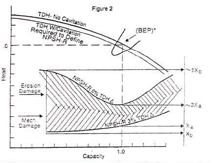
What it IS is a measure of the inlet head at the point at which the differential head is lowered by 3% for various flowrates to generate a curve.

What it IS NOT is an indication of the onset of cavitation. That's because it is quite difficult to measure and define.

So normally a designer would require at least 1m and possibly up to 3m above the NPSH figure to prevent long term cavitation and damage to the pump.

0.5m sounds like a recipe for long term cavitation and damage to the pump.

If you ask the vendor nicely he might give you a graph of onset of cavitation vs flow and it might look something like this.

NPSH_jnszdy.jpg


Remember - More details = better answers
Also: If you get a response it's polite to respond to it.
 
That's one of the best articles I've ever seen on the theory of NPSHR versus reality.

I learnt my lesson using a pump downstream of a vacuum de-aration tower. Even when I was within >0.5m of the NPSHR, the pump was audibly cavitating.

Pump vendor was good and eventually we came to the conclusion to use a bigger impellor and a 4 pole machine reducing speed to 1500 RPM. With the pump already in a pit I couldn't go physically lower but that seemed to work out OK.

They did actually provide the onset of cavitation curve and it was a lesson well learnt - NPSHR isn't cavitation.

maatoug,

Your issue is possibly what the impact of those "trace" elements are. They may actually help if they create small bubbles which can absorb the cavitation bubbles. But if you get too many bubbles your pump discharge will drop and you may loose suction.

What is your actual inlet pressure though if you're at 90C?

Some actual inlet and NPSH curves would help a lot there.

Remember - More details = better answers
Also: If you get a response it's polite to respond to it.
 
My turn .....

Thank You LittleInch ....After many years of practice,I am getting pretty good at this google thingamabob ...

As always, Littleinch offers sage advice and I agree with his statements above.

I want to emphasize:

FIRST: If you remember anything from this thread, it is the understanding that meeting the pump NPSHr of your particular circumstance is an approximate (but not absolute) assurance that cavitation will not be an operational assurance Having an adequate NPSHa margin is an assurance of long term pump operational reliability

SECOND: We are designing and evaluating very coarse machines here ! ... These are industrial centrifugal pumps not swiss watches ! ... A description by the OP of a 0.5m margin on the NPSHa is silly

THIRD: The competent and proper evaluation of the NPSH by the process pump engineer separates the men from the boys! There is no "quickie" rule of thumb that can be used by the newbie which will work in all circumstances. The OP does not seem to understand this and his dependence on a "one meter" rule is bad advice, IMHO. A competent evaluation should include detailed vendor information; information about liquid entrained gasses and solids; impeller materials and finish, system temperature and pressure upsets; etc

There are many fine technical books and papers available on the internet. (Especially useful are the TAMU papers) Because there are so many subtle facets to this problem, I urge all pump engineers who are serious about their career to develop and use a personal binder with pump NPSH reference papers.

Anybody else here ???

MJCronin
Sr. Process Engineer
 
You might consider reading through (and applying) the hydraulic institute ANSI/HI 9.6.1 - Guideline for NPSH Margin and ANSI 9.6.3 - Guideline for Operating Regions. I think that you will find that HI will indicate that 0.5 m is not adequate. Some have admittedly argued that the HI published values are not conservative enough as they may not represent full suppression of cavitation. There is a legacy of readily available papers (see google) that indicate that full suppression of cavitation requires a margin ratio (NPSHA/NPSH3) greater than 4.0 near the best efficiency point (which is not always practical nor cost effective to achieve) - This becomes more of a consideration if your application drifts outside the pump's preferred operating range and/or the pump's allowable operating range.

Be careful out there.


A bare minimum is 1m margin between NPSHr at max normal operating flow and NPSHa at min operating level ( level low low) in the source vessel.
Also take into account whether the pump vendor has done an NPSHr test with your operating fluid in their quote to you.
Other things that affect how the pump will behave are (i) whether there is sufficient liquid degassing capacity at max operating flow at low low level in the source vessel (ie between low low level and top of vortex breaker)(ii) the pump nozzle orientation should permit self venting of the pumping chamber (iii) whether you have provided adequate additional press drop for a fouled suction strainer at max flow.
The statement " trace amounts of condensate" may be somewhat misleading - what if you had poor interface level control, and then you have much than just a trace amount of condensate in the feed to this pump? What does this do to NPSHa and NPSHr - have you done these calcs based on condensate vapor pressure? It is very common for this to occur in actual operations; high shear of the feed liquid phase, chemicals with surfactant properties in the liquid that promote emulsions, poor interface level detection.
 
And don't forget the CO2 in the solution, that may come out of solution at the pump inlet so you may have a two phase flow situation to begin with.

= = = = = = = = = = = = = = = = = = = =
P.E. Metallurgy, consulting work welcomed
 
Good day all,

Looking at the opening statement, the first "variable" that strikes me, is the design temperature, 90 deg (vapour pressure). The liquid needs a lot of atmospheric pressure in order to keep it in liquid form. Or is it in a closed tank? Is the suction liquid level above/below the pump center line? Design pressure 11 bar, operating pressure 4 bar???? Bit of a difference there?
Besides the NPSHA/NPSHR been in question here. I would want to see the suction piping layout, to ensure that we are not entertaining cavitation issues, due to velocities, bends before the pump inlet, turbulence etc.
 
Status
Not open for further replies.
Back
Top